

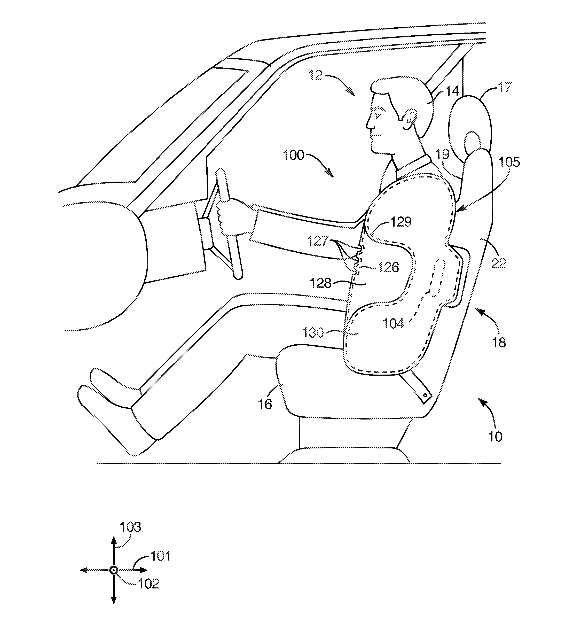
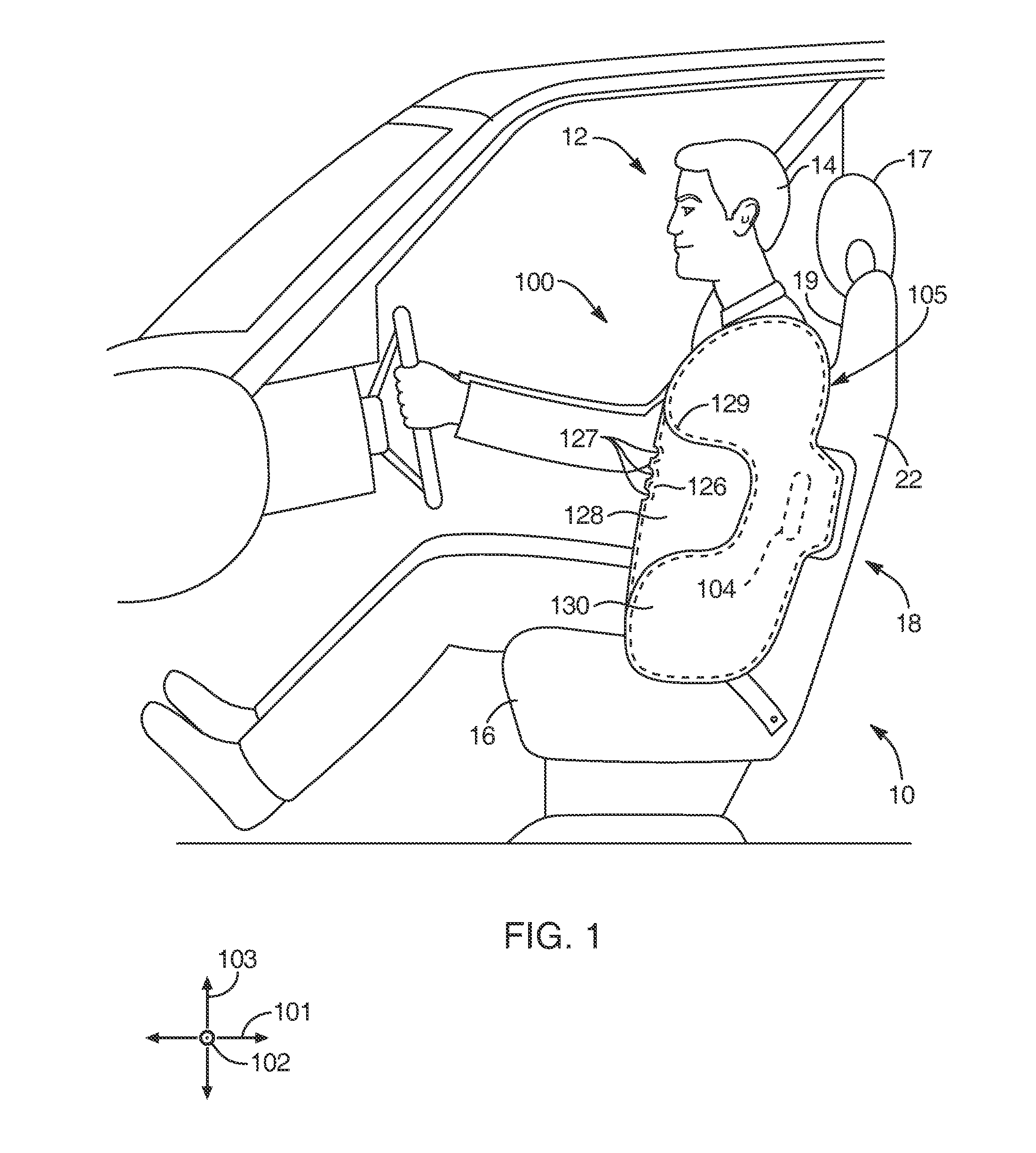
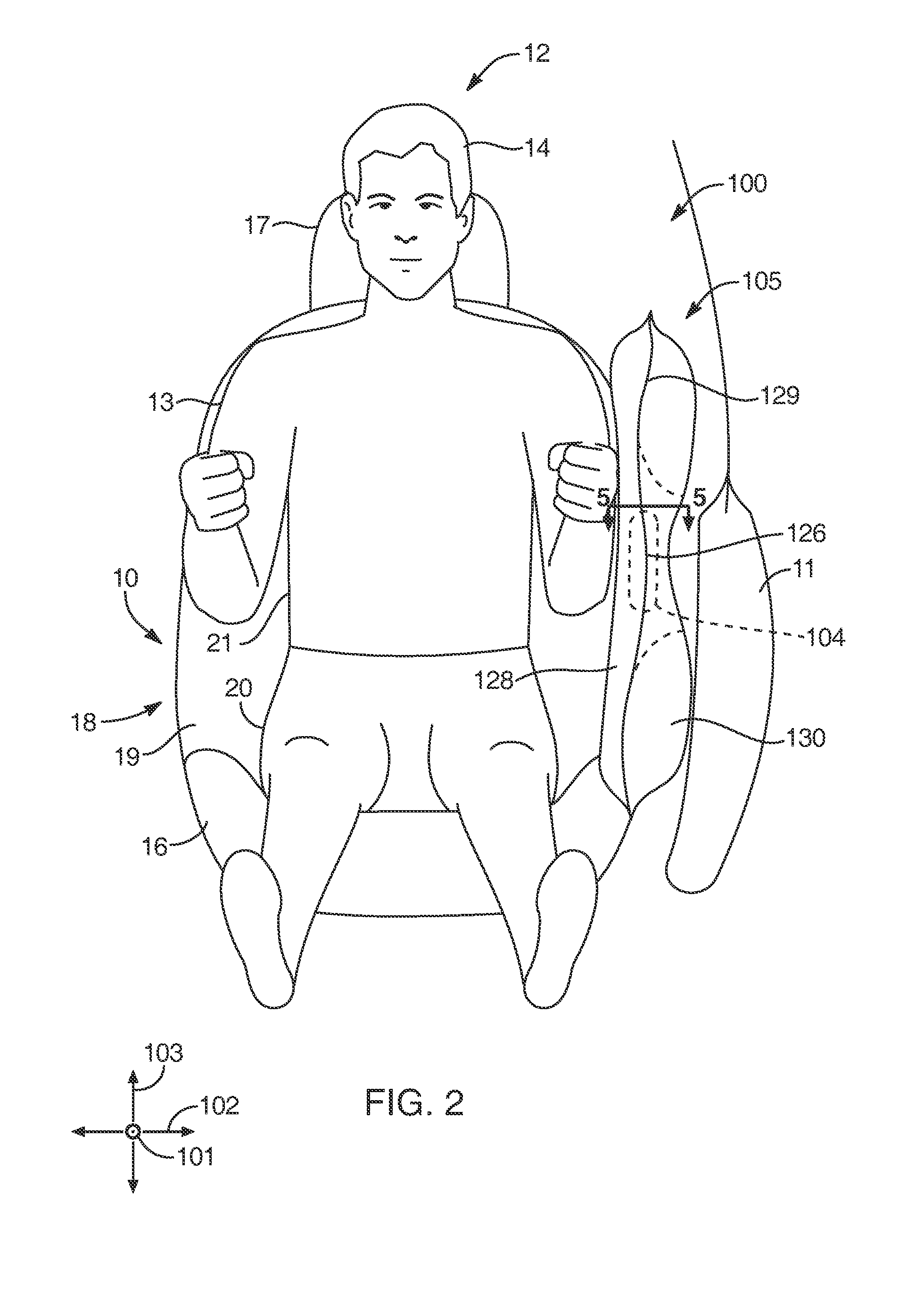
3-layer "c" shaped side airbag
a side airbag and 3 layer technology, applied in the direction of pedestrian/occupant safety arrangement, vehicle components, vehicular safety arrangments, etc., can solve the problems of affecting the vehicle surface, requiring a greater degree of cushion rigidity, and insufficient rigidity of the cushion, so as to reduce manufacturing and installation costs.
- Summary
- Abstract
- Description
- Claims
- Application Information
AI Technical Summary
Benefits of technology
Problems solved by technology
Method used
Image

Examples
Embodiment Construction
[0031]Exemplary embodiments of the invention will be best understood by reference to the drawings, wherein like parts are designated by like numerals throughout. It will be readily understood that the components of the invention, as generally described and illustrated in the Figures herein, could be arranged and designed in a wide variety of different configurations. Thus, the following more detailed description of the embodiments of the apparatus, system, and method, as represented in FIGS. 1 through 8, is not intended to limit the scope of the invention, as claimed, but is merely representative exemplary of exemplary embodiments of the invention.
[0032]The phrases “connected to,”“coupled to” and “in communication with” refer to any form of interaction between two or more entities, including mechanical, electrical, magnetic, electromagnetic, fluid, and thermal interaction. Two components may be functionally coupled to each other even though they are not in direct contact with each o...
PUM
 Abstract
Description
Claims
Application Information