Power control system, power control apparatus and power control method

a power control and power control technology, applied in secondary cell servicing/maintenance, sustainable manufacturing/processing, greenhouse gas reduction, etc., can solve the problems of increasing the output power of the photovoltaic module, the load cannot be supplied any more, and the power consumption of the load increases rapidly. to achieve the effect of stable power supply

Active Publication Date: 2015-04-09
KYOCERA CORP
View PDF13 Cites 21 Cited by
  • Summary
  • Abstract
  • Description
  • Claims
  • Application Information

AI Technical Summary

Benefits of technology

[0021]According to one of the aforementioned aspects, the second controller increases, during a self-sustaining operation, a charging power to the storage battery, detects output fluctuation from the photovoltaic module or from the first controller with an increase in the charging power, and, based on the detected output fluctuation, controls the charge to the storage battery, thereby allowing stable power supply from a photovoltaic module to a load even if connection with a grid is disconnected.

Problems solved by technology

In these circumstances, for example, when many electrical appliances are operated at the same time and the power consumption by the load increases rapidly, output power from the photovoltaic module increases rapidly following thereto.
Then, when it is expected that the output power exceeds the power generation, the PV power conditioner performs a safety-centered control by which the output power is stopped, thus load power cannot be supplied any more.

Method used


Image

  • Power control system, power control apparatus and power control method
  • Power control system, power control apparatus and power control method
  • Power control system, power control apparatus and power control method

Examples


Embodiment Construction

[0026]In the following, embodiments according to the present invention will be described with reference to the drawings. However, the technical scope of the present invention is not limited to these embodiments, and includes the matters and their equivalents described in the scope of claims.

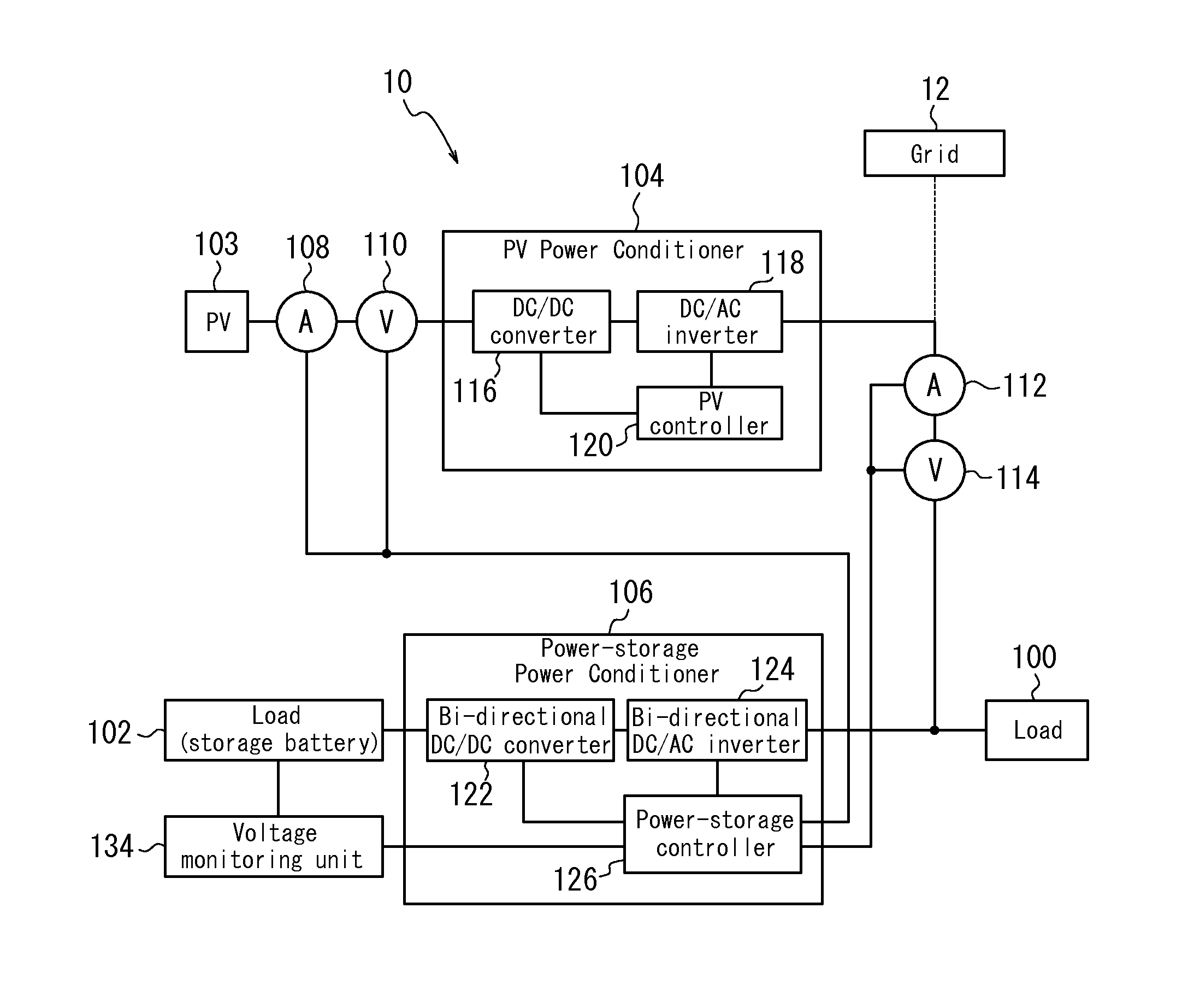
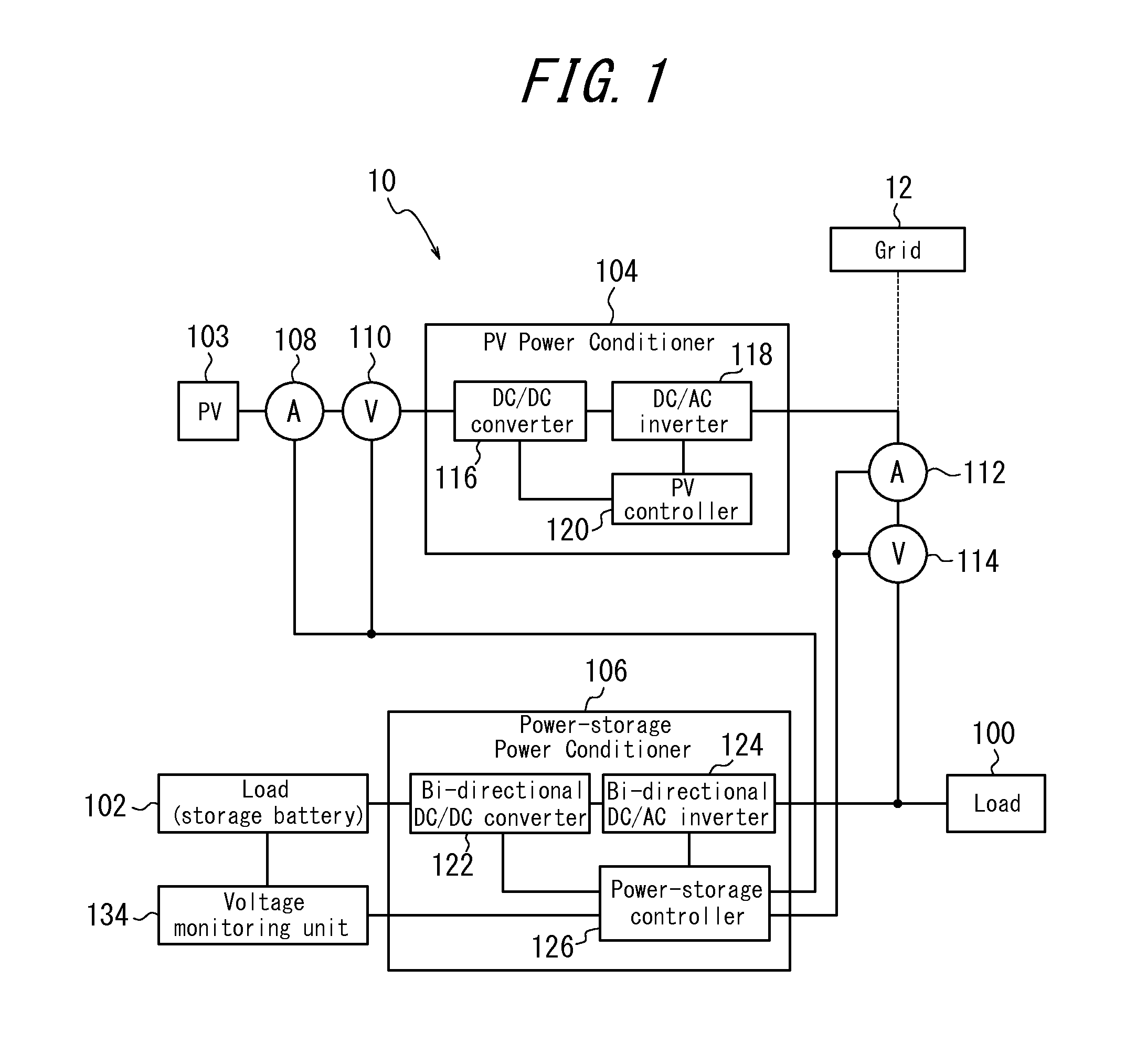
[0027]FIG. 1 is a diagram illustrating a configuration example of a distributed power generation system to which a control apparatus according to the present embodiment is applied. The distributed power generation system 10 is provided, for example, in household or various commercial and industrial facilities, and the power generated by a photovoltaic module 103 is supplied to loads 100 and 102 in household or facilities. For the photovoltaic module 103, for example, power generation units each having a photoelectric conversion cell are connected in a matrix manner and a predetermined short-circuit current (e.g. 10A) is output. As the photovoltaic module 103, any type such as silicon polycrystal ...


PUM


Abstract

In a power control system including a first controller configured to control supply of power from a photovoltaic module to a plurality of loads and a second controller configured to control charge/discharge of a storage battery, which is one of the plurality of loads, the first controller controls output following power consumption by the plurality of loads, and the second controller increases, during a self-sustaining operation, charging power of the storage battery and detects output fluctuation from the photovoltaic module or from the first controller along with the increase in the charging power, then based on the detected output fluctuation, controls charge of the storage battery, thus, even if connection to the grid is disconnected, supply power may be replenished by the load power used for supply to the predetermined loads, thereby allowing a stable power supply to the other loads.

Description

CROSS REFERENCE TO RELATED APPLICATION[0001]The present application claims the priority of Japanese Patent Application No. 2012-047088 filed on Mar. 2, 2012, the content of which is entirely incorporated herein by reference.FIELD[0002]The present invention relates to a control system configured to control power supply from photovoltaic modules to loads, a control apparatus and a control method.BACKGROUND[0003]In the context of environmental issues and safety requirements, power generation by sunlight or wind power has attracted attention. For example, there is a growing number of households that introduce a photovoltaic power generation system. In the photovoltaic power generation system, the power generated by a photovoltaic module is supplied to the domestic electric power load (hereinafter referred merely to as load). Then, when the power generation exceeds the power consumption by the load, the excess power generation is fed back and sold to the commercial power grid (hereinafte...

Claims


Application Information

Patent Timeline
Patent Type & Authority Applications(United States)
IPC IPC(8): H02J3/32H02J7/35
CPCH02J7/35H02J3/32H01M10/441H01M10/465Y02E70/30Y02P90/50H02J2300/24H02J3/381Y02B10/10Y02E10/56Y02P80/20Y02E60/10H02J3/388
Inventor TAKENAKA, TETSUYA
Owner KYOCERA CORP
Why Eureka
Try Eureka