Object tracking based on dynamically built environment map data

a dynamically built environment and map data technology, applied in image analysis, instruments, computing, etc., can solve the problems of significant tracking jitter, loss of accuracy of estimated camera pose, loss of tracking robustness, etc., to extend the range of trackable poses and improve the tracking robustness of any trackable object.

Active Publication Date: 2015-04-09
QUALCOMM INC
View PDF2 Cites 50 Cited by
  • Summary
  • Abstract
  • Description
  • Claims
  • Application Information

AI Technical Summary

Benefits of technology

[0008]Some embodiments discussed herein provide for improved tracking robustness of any trackable object and may extend the range of trackable poses beyond the visible range of the target. Embodiments discussed herein may be applied to any augmented reality (AR) system that is based on tracking a reference target. In one aspect, a tracking system estimates the target p

Problems solved by technology

A challenge to enabling Augmented Reality (AR) on mobile phones or other mobile platforms is the problem of detecting and tracking objects in real-time.
If the target object is small, partially occluded, or lacks distinctive visual features, then the estimated camera pose l

Method used


Image

  • Object tracking based on dynamically built environment map data
  • Object tracking based on dynamically built environment map data
  • Object tracking based on dynamically built environment map data

Examples


Embodiment Construction

[0018]Reference throughout this specification to “one embodiment”, “an embodiment”, “one example”, or “an example” means that a particular feature, structure, or characteristic described in connection with the embodiment or example is included in at least one embodiment of the present invention. Thus, the appearances of the phrases “in one embodiment” or “in an embodiment” in various places throughout this specification are not necessarily all referring to the same embodiment. Furthermore, the particular features, structures, or characteristics may be combined in any suitable manner in one or more embodiments. Any example or embodiment described herein is not to be construed as preferred or advantageous over other examples or embodiments.

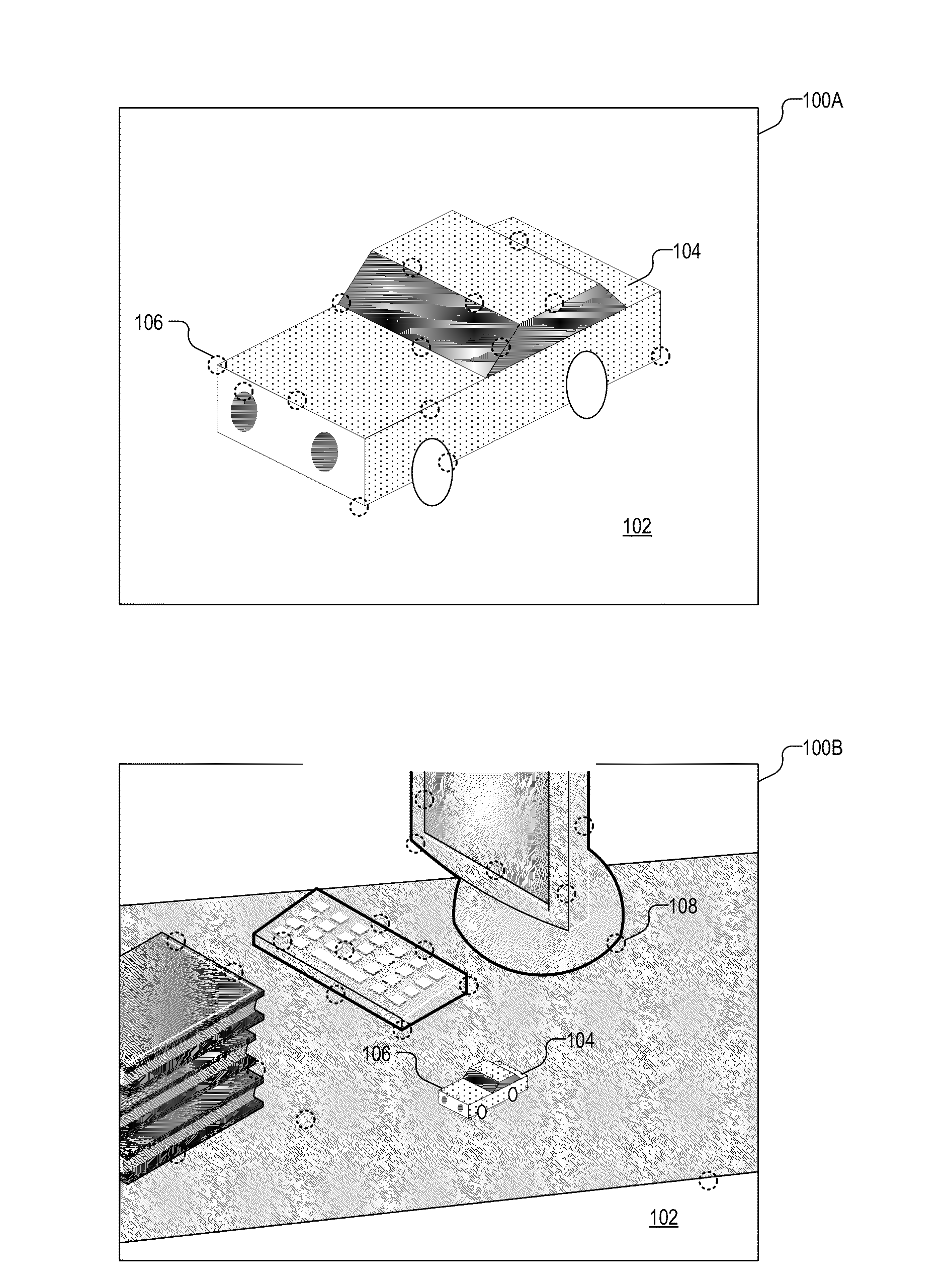
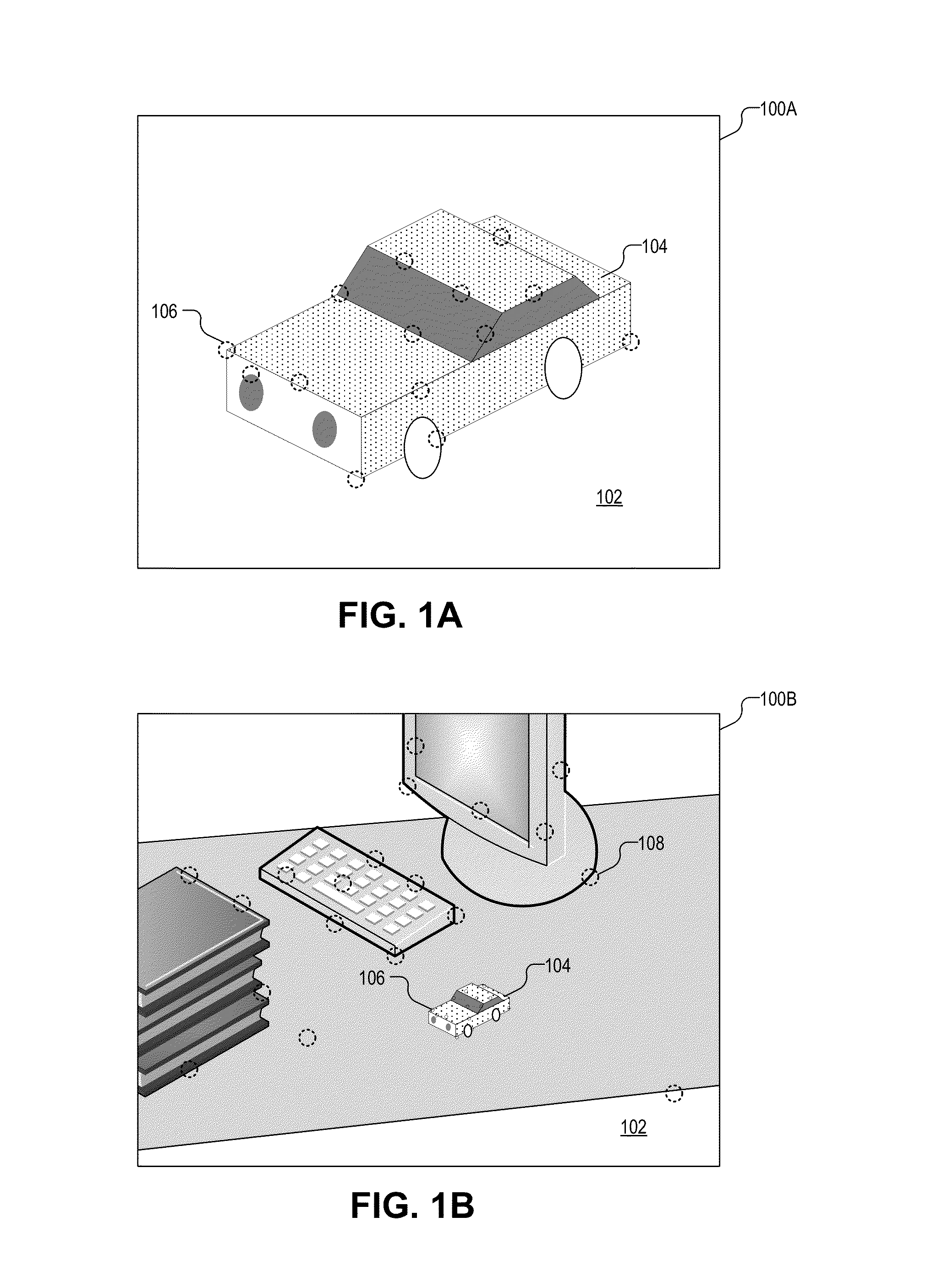
[0019]In one aspect, using environment map data in the tracking of a target object improves tracking robustness of any trackable object and extends the range of trackable poses beyond the visible range of the target and can even increase the trackin...


PUM


Abstract

A computer-implemented method of tracking a target object in an object recognition system includes acquiring a plurality of images with a camera. The method further includes simultaneously tracking the target object and dynamically building environment map data from the plurality of images. The tracking of the target object includes attempting to estimate a target pose of the target object with respect to the camera based on at least one of the plurality of images and based on target map data. Next, the method determines whether the tracking of the target object with respect to the camera is successful. If not, then the method includes inferring the target pose with respect to the camera based on the dynamically built environment map data. In one aspect the method includes fusing the inferred target pose with the actual target pose even if tracking is successful to improve robustness.

Description

CROSS-REFERENCE TO RELATED APPLICATION[0001]This application claims the benefit of U.S. Provisional Application No. 61 / 887,211, filed Oct. 4, 2013.TECHNICAL FIELD[0002]This disclosure relates generally to computer vision based object recognition applications, and in particular but not exclusively, relates to object tracking in an augmented reality system.BACKGROUND INFORMATION[0003]A challenge to enabling Augmented Reality (AR) on mobile phones or other mobile platforms is the problem of detecting and tracking objects in real-time. Object detection for AR applications has very demanding requirements: it must deliver full six degrees of freedom, give absolute measurements with respect to a given coordinate system, be very robust and run in real-time. Of interest are methods to compute camera pose using computer vision (CV) based approaches, which rely on first detecting and, subsequently, tracking objects within the camera view. In one aspect, the detection operation includes detecti...

Claims


Application Information

Patent Timeline
IPC IPC(8): G06K9/00G06T19/00
CPCG06T19/006G06K9/00624G06V20/20G06T7/33G06V20/00G06F18/217
Inventor GEE, ANDREWPAN, QIGERVAUTZ, MICHAEL
Owner QUALCOMM INC
Why Eureka
Try Eureka