Electric connector

a technology of electrical connectors and connectors, applied in the direction of coupling devices, coupling devices with two parts, coupling devices, etc., can solve the problems of deterioration in reliability of electrical connection between male and female connectors, and the electric connectors are accompanied by problems such as deterioration in reliability of electrical connection, so as to enhance the reliability of electrical connection and increase the proof stress

Inactive Publication Date: 2015-04-09
DAIICHI SEIKO CO LTD
View PDF8 Cites 18 Cited by
  • Summary
  • Abstract
  • Description
  • Claims
  • Application Information

AI Technical Summary

Benefits of technology

[0010]In view of the above-mentioned problems in the conventional electric connectors, it is an object of the present invention to provide an electric connector capable of having an increased proof stress to axial rotation to thereby enhance reliability to electrical connection between male and female connectors.

Problems solved by technology

However, the conventional electric connectors are accompanied with a problem that if they are oscillated or they receive impact when a male connector is fit into a female connector, one of the connectors is forced to axially rotate, resulting in that the one of the connectors gradually retreats, and thus, the male connector might be released from the female connector.
However, if an intensive force acts on the male and female connectors in a direction of the axial rotation, the projection would be collapsed, resulting in that one of the male and female connectors makes relative axial rotation.
Thus, the conventional electric connectors are accompanied with a problem of deterioration in reliability to electrical connection between the male and female connectors.

Method used


Image

  • Electric connector
  • Electric connector
  • Electric connector

Examples


Embodiment Construction

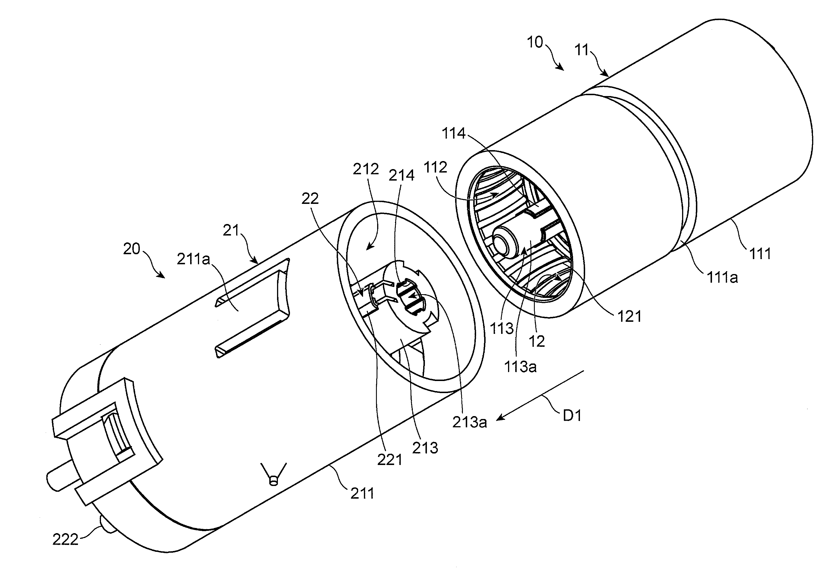
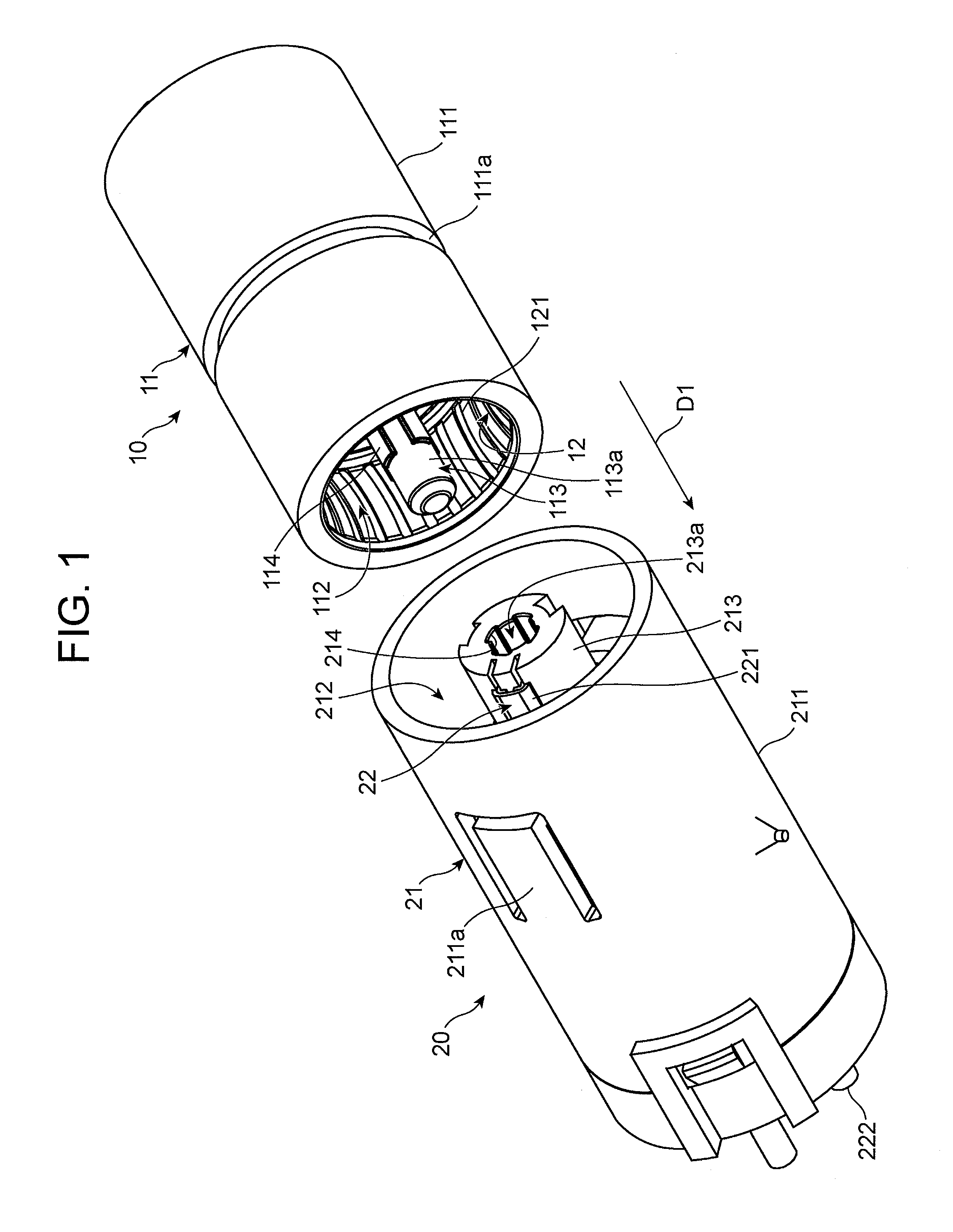
[0044]FIG. 1 is a perspective view of the electric connector in accordance with the preferred embodiment of the present invention.

[0045]As illustrated in FIG. 1, the electric connector includes a male connector 10 and a female connector 20.

[0046]The male connector 10 and the female connector 20 are used for connecting a various kinds of a sensor to a wire harness, for instance.

[0047]First, the male connector 10 is explained hereinbelow.

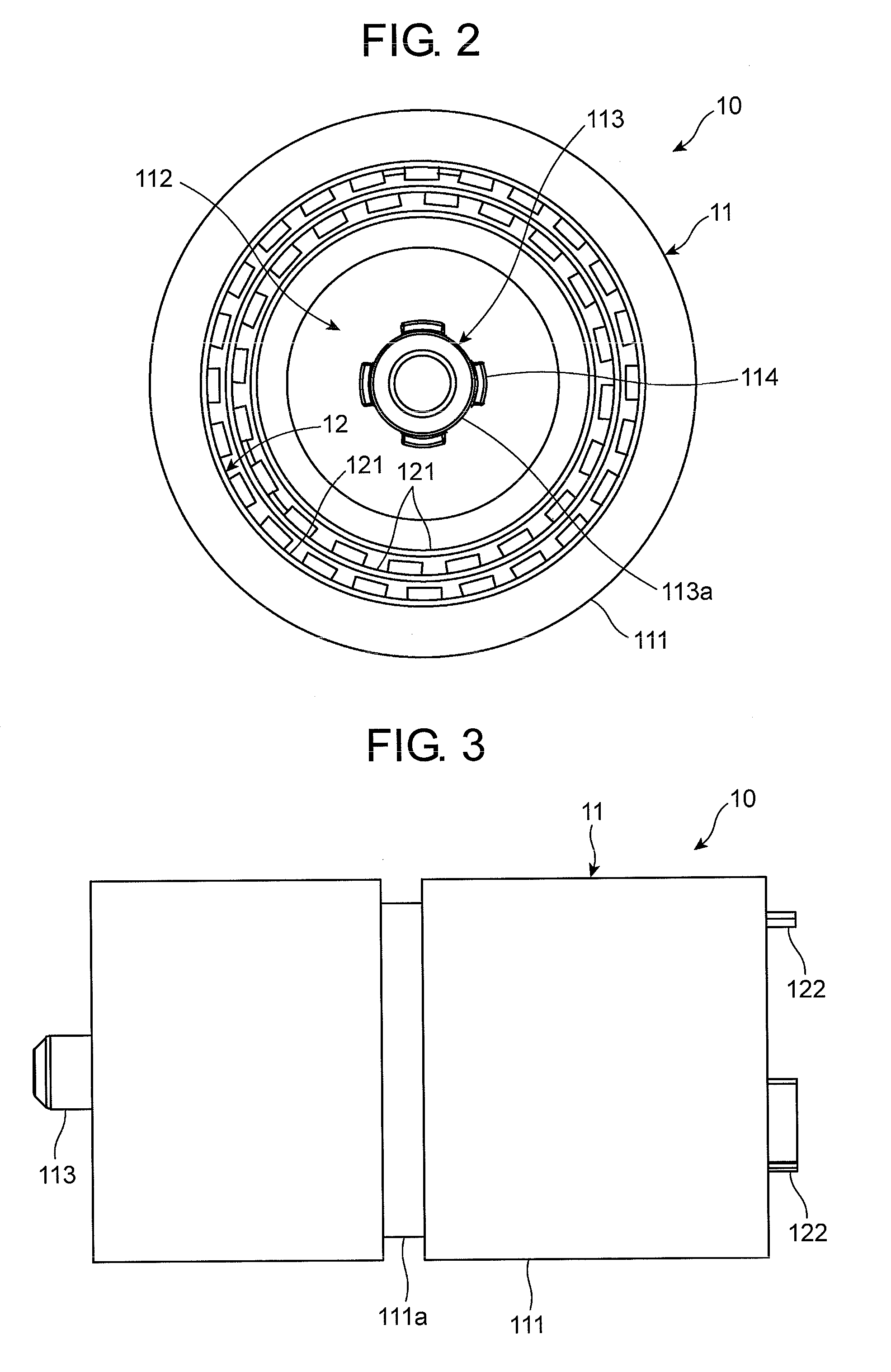
[0048]As illustrated in FIGS. 1 to 3, the male connector 10 includes a male housing 11 to be fit into the female connector 20, and three male contact terminals 12 electrically connecting the male connector 10 to the female connector 20.

[0049]The male housing 11 includes a cylindrical main body 111 open at one end and closed at the other end to thereby define a hollow space 112 therein, and a guide shaft 113 extending in the hollow space 112 in a direction D1 in which the male connector 10 is fit into the female connector 20.

[0050]The main body 111 is ...


PUM


Abstract

An electric connector includes a first housing including a guide shaft and a second housing including a guide hole into which the guide shaft is inserted, the guide shaft including a main body, and a projection radially projecting from the main body, the guide hole being formed at an inner surface thereof with a groove into which the projection is fit, the projection and the groove being formed such that a first imaginary line intersects with a second imaginary line, the first imaginary line being defined by extending a contact plane at which the projection and the groove make contact with each other when the first housing rotates relative to the second housing, towards a center of the main body, the second imaginary line being defined as a line bisecting a top surface of the projection and extending towards a center of the main body.

Description

BACKGROUND OF THE INVENTION[0001]1. Field of the Invention[0002]The invention relates to an electric connector including a first housing of a male connector, and a second housing of a female connector into which the first housing is fit.[0003]2. Description of the Related Art[0004]An electric connector, such as a connector used for a glow plug igniting and / or pre-heating an engine and a connector connecting a combustion-pressure sensor and a wire harness to each other, generally includes a cylindrical male connector. Since the male connector is designed to be symmetrical in rotation relative to a female connector, the male connector can be fit into the female connector even if the male connector is rotated in any direction around an axis of the male connector. Thus, the male connector can be readily fit into the female connector even manually, even if those connectors are located at a place where an operator cannot see the connectors.[0005]FIG. 15 illustrates the electric connector ...

Claims


Application Information

Patent Timeline
Patent Type & Authority Applications(United States)
IPC IPC(8): H01R13/629H01R24/58
CPCH01R24/58H01R13/629H01R13/631H01R24/38H01R24/86
Inventor HASHIMOTO, YOSHIMITSUJINNOUCHI, SHOGO
Owner DAIICHI SEIKO CO LTD
Why Eureka
Try Eureka