Bonded member comprising different materials and production method thereof

a technology of bonded members and different materials, applied in the field of bonded members, can solve the problems of unfavorable increase in production costs of these composite members, inability to achieve desired bonding strength and air tightness, and cracks in the vicinity of the interface, so as to achieve the effect of reducing the proof stress of au soldering materials and hardly lowering the bonding strength of bonded members

Inactive Publication Date: 2005-04-19
NGK INSULATORS LTD
View PDF11 Cites 5 Cited by
  • Summary
  • Abstract
  • Description
  • Claims
  • Application Information

AI Technical Summary

Benefits of technology

[0021]Thus, according to the method of the present invention for producing a bonded member comprising different materials, a ceramic base material and a metal member which are different types of materials are solid-phase bonded via a soldering material comprising Au (precoat layer) and a barrier layer, or a ceramic base material and a metal member comprising Cr or an alloy containing Cr as a major component are solid-phase bonded via a soldering material comprising Au. Accordingly, there can be obtained a bonded member in which diffusion of a metal material such as Ni, which such a metal material hardens severely the Au soldering material when such a metal material is dissolved and solidified in the Au soldering material, into the soldering material is prevented and an unfavorable increase in proof stress of the Au soldering material are suppressed by the barrier layer even when the bonded member according to the present invention is used at a higher temperature. Thus, the bonding strength of the bonded member is hardly lowered even at a higher temperature. The bonded member comprising different materials according to the present invention is a bonded member comprising different materials being producible by the foregoing production method of the present invention.

Problems solved by technology

However, during a cooling process in high-temperature bonding, since thermal stress is generated due to the difference in thermal expansion coefficient between the different materials or between the soldering material used for bonding the different materials together and the materials, cracks are formed in the vicinity of the interface when one of the members is brittle, or the separation occurs at the interface between the members.
Accordingly, the desired bonding strength and air tightness may not be able to be attained in some cases.
Since products having aforementioned troubles broken during a production process must be discarded as defective products, this results in an unfavorable increase in production cost of these composite members.
Further, if the product is subjected to thermal cycle in use, these troubles often occur after use for a certain time period to cause deterioration of reliability of the product.
Meanwhile, in these methods, unless some measures are taken against thermal stress which occurs at the interface between the bonded materials, the ceramic base material which is vulnerable to the thermal stress may often be cracked or separation may occur at the interface, so that bonding strength as well as various properties required as a composite member such as air tightness may be influenced.
Particularly, it is very difficult to bond a low-strength member such as aluminum nitride to a different material such as a metal material with the above problems inhibited from occurring.
However, in a case where Ag or Cu is used, they may be difficult to use in some cases due to a problem caused by oxidation of the soldering material when a bonded member is exposed to an application environment of 400° C. or higher under oxidizing atmosphere, a problem caused by volatilization of the soldering material caused by their high vapor pressures when they are used at a high temperature and a low pressure, a problem of migration when energized and used, or a problem of a reaction with an Mo oxide.
As a result, residual stress at the time of bonding cannot be absorbed sufficiently by plastic deformation of the soldering material, and bonding strength lowers due to heat applied upon or after completion of the bonding.
Consequently, when the bonded member undergoes a thermal cycle or thermal shock is given thereto, the ceramic base material may be cracked.
Further, it is known that when an Au-18Ni soldering material and a conductive material (Mo) are bonded together, Ni in the soldering material reacts with Mo and forms a brittle structure.
Accordingly, when use of a resulting binding component as a member for a high-temperature heater is considered, there arises a problem that durability of the component when the interface between bonded members is exposed to a thermal cycle and thermal shock lowers and sharply deteriorates, thereby preventing further use of the component.
Further, when kovar is used as the metal material, for example, components (Fe, Ni, Co) constituting Kovar are diffused into the soldering material when the base material and Kovar are bonded together and form an intermetallic compound having low conductivity, so that there arise problems of deterioration of thermal properties and occurrence of abnormal heat generation at the site.
However, these metal materials have a problem that they are oxidized vigorously at a high temperature in air and cannot be used as a metal material for a high-temperature heater exposed to conditions such as mentioned above.
However, the bonded structure has such problems that the number of components is large and that if the atmosphere protecting member 10 and the metal member 17 are not fully bonded to each other, deterioration occurs due to oxidation of the metal member 17, so that a very high production control ability is required.
However, although adoption of such a member structure is effective for alleviation of thermal stress, since a Cu-based soldering material is used, usable temperatures are limited due to such problems as oxidation of the soldering material and evaporation of the soldering material caused by a vapor pressure.
Consequently, when a composite member which comprises a ceramic base material having an Au soldering material as a precoat layer and a metal member comprising Ni or the like is used as a member for an electrical apparatus exposed to temperatures exceeding 700°C. upon use, for example, a susceptor for mounting a semiconductor wafer, a problem that the ceramic base material cracks within a relatively short period is liable to occur.
However, when Ti is used for bonding ceramic to a soldering material, Pt cannot be used as a barrier layer.
For example, when ceramic and a metal material coated with Pt are bonded together by use of Au and Ti, bonding between Au and ceramic does not occur effectively when liquid phase bonding disclosed in JP-A-199775 / 2001 is carried out.
It is understood that this is because Ti fused into Au is drawn to the Pt layer due to good affinity between Pt and Ti, and resultantly this causes the shortage of Ti to be used for the formation of a TiN reaction layer at the interface.
Accordingly, the formation of the TiN layer is unsatisfactory and bonding strength between the Au soldering material and ceramic is lowered.
Furthermore, the bonding strength is also lowered due to Karkendal voids occurring in the vicinity of the interface of the Pt coating material upon movement of these atoms.
Therefore, this method is difficult to be employed for the production of bonded members for certain use.

Method used


Image

  • Bonded member comprising different materials and production method thereof
  • Bonded member comprising different materials and production method thereof
  • Bonded member comprising different materials and production method thereof

Examples


examples

[0051]Hereinafter, examples of the present invention will be described. However, it is needless to say that the present invention shall not be limited to the following examples.

examples 1 to 8

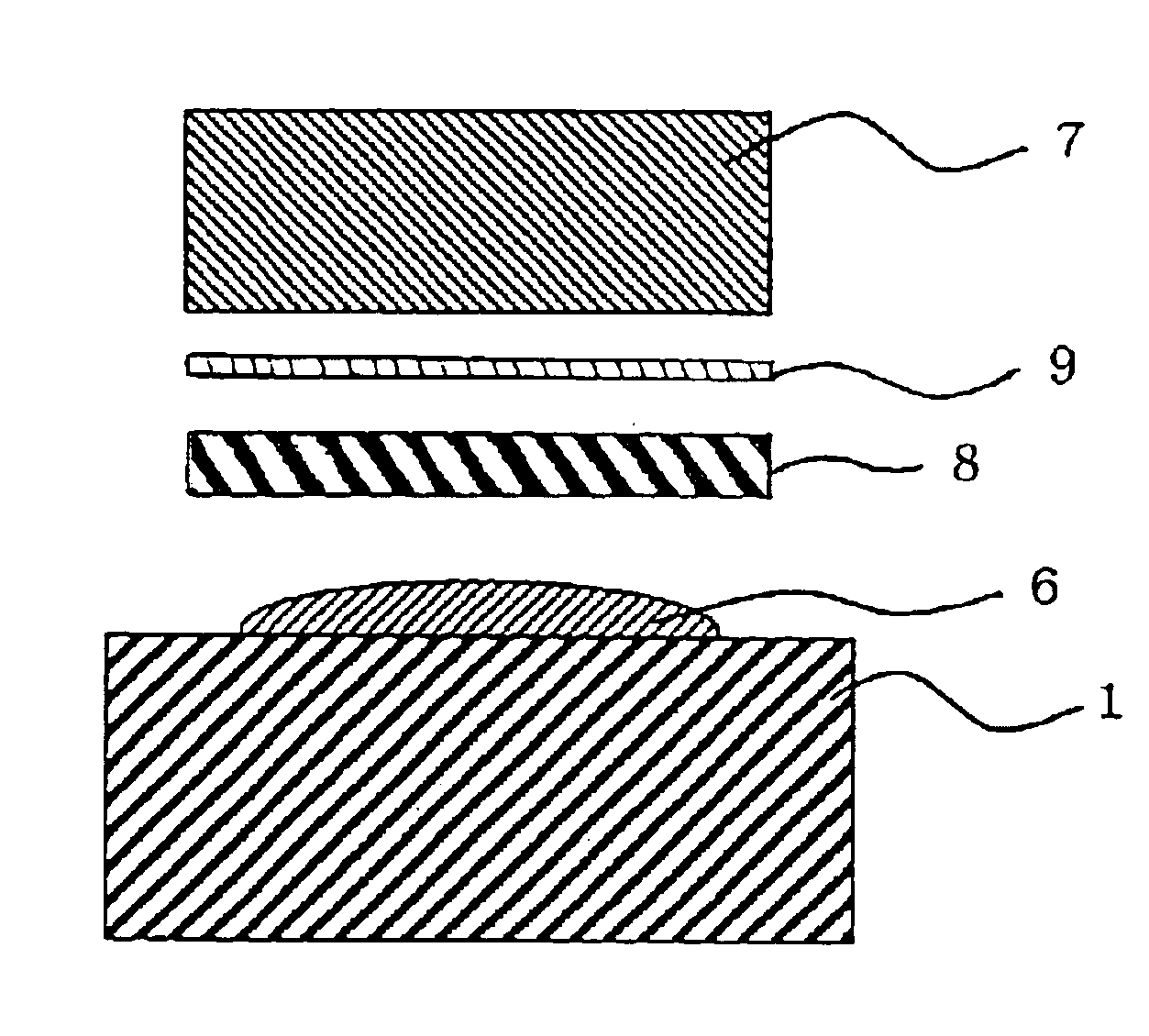
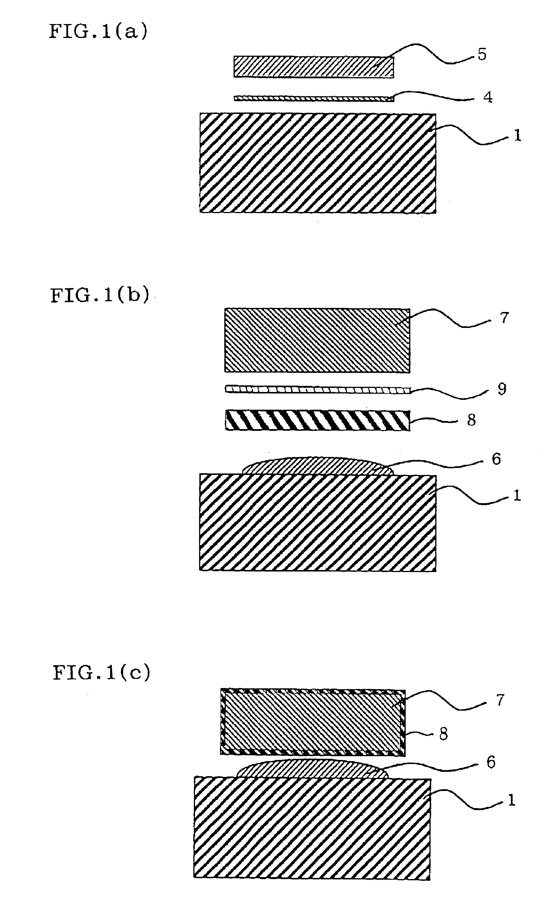
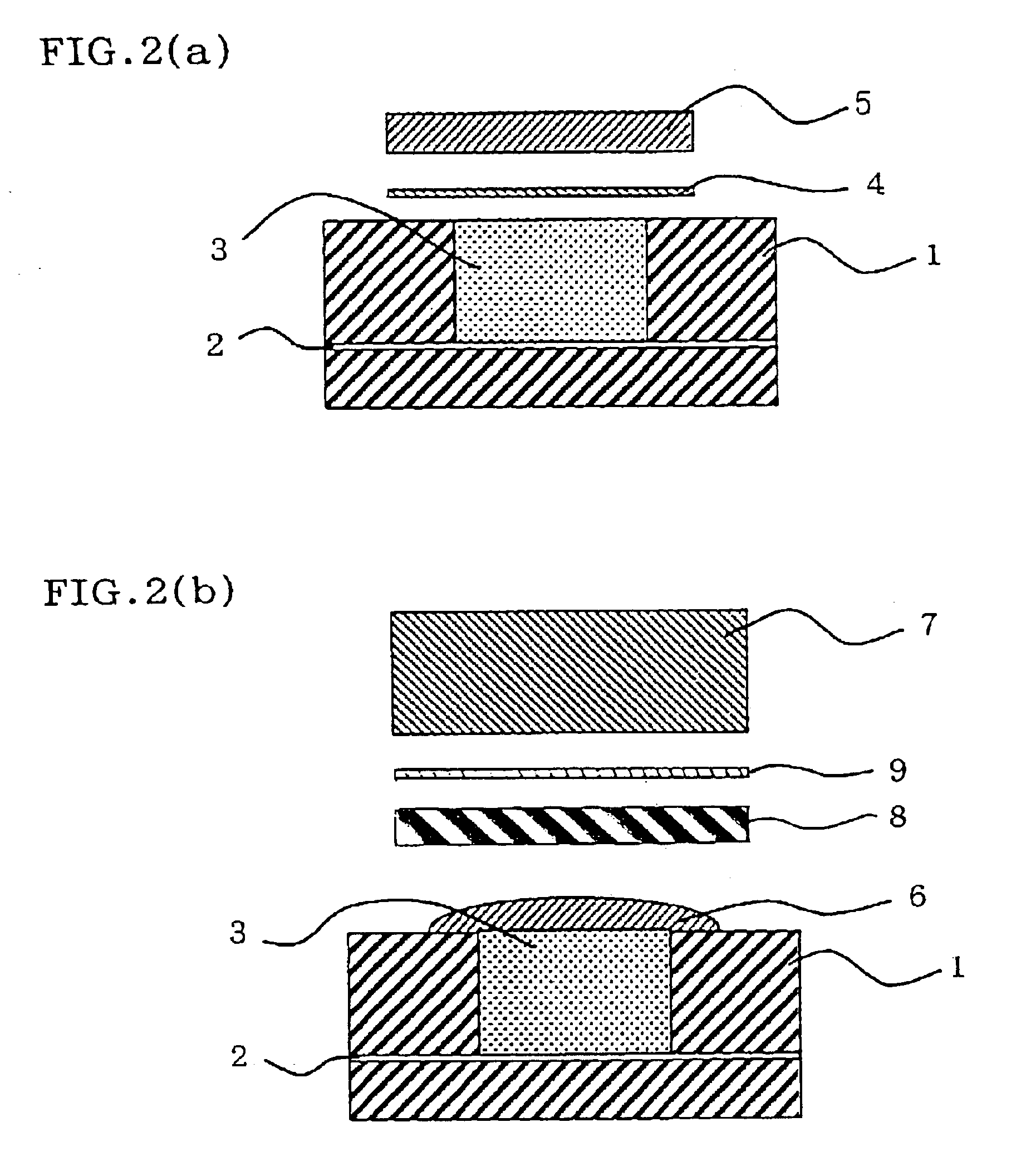
[0052]On an AlN ceramic base material (sintered body with an AlN purity of 99.9%, flexural strength: 360 MPa), 5 μm Ti foil and a 1,000 μm pure Au soldering material were placed, and they were molten by heating in a vacuum atmosphere at 1,100° C. for 10 minutes so as to form an Au precoat layer (thickness: 800 μm). As a result of measuring the hardness (Vickers hardness (load: 100 g) Hv0.1) of the precoat layer, it was found to be 45 to 55. Further, when these bonded layers were removed by grinding so as to check occurrence of cracks in AlN, it was found that no cracks occurred in AlN.

[0053]On the precoat layer, a pure Cr plate having a thickness of 2 mm and a diameter of 6 mm, pure Au having a thickness of 200 μm, and an Inconel 601 (Fe-61Ni-23Cr-1.4Al) or Ni terminal having a diameter of 5 mm and a length of 20 mm were placed in order mentioned above. Then, they were heated in a vacuum atmosphere under a load of 10 MPa at 800° C. for 1 hour so as to be solid-phase bonded Examples ...

examples 9 to 13

[0056]As in the foregoing Examples 1 to 8, a precoat layer was formed on an AlN ceramic base material, a Kovar (Fe-29Ni-17Co) or Ni terminal having a diameter of 5 mm and a length of 20 mm and plated with Cr to a thickness of 20 μm was placed on the precoat layer, and they were solid-phase bonded at 800° C. for 1 hour under a load of 10 MPa Examples 9 and 11.

[0057]The foregoing bonded member having the Ni terminal was kept in air at 700° C. for 100 hours Example 10, while the foregoing bonded member having the Kovar terminal was kept in air at 700° C. for 100 hours or 800° C. for 100 hours Examples 12 or 13. In all these bonded members, the hardness Hv0.1 of the precoat layer was 45 to 55, which was found to be unchanged. When the bonded layers were removed by grinding so as to check occurrence of cracks in AlN, it was found that no cracks occurred in AlN. The foregoing tensile test was conducted on the bonded members of the foregoing Examples 9 to 13. The results are shown in Table...


PUM

PropertyMeasurementUnit
thicknessaaaaaaaaaa
temperatureaaaaaaaaaa

Abstract

A bonded member includes a ceramic base material and a metal member solid-phase bonded via a soldering material. An active metal is placed on a surface of the ceramic base material and the soldering material, which includes Au, is placed on the active metal, and the active metal and the soldering material are heated so as to form a precoat layer. The metal member is placed on the surface of the precoat layer via a barrier layer, which is capable of inhibiting diffusion of a metal constituting the metal member, and the precoat layer and the metal member are pressurized heated so as to be solid-phase bonded. The production method of the bonded member is also disclosed.

Description

BACKGROUND OF THE INVENTION[0001]1. Field of the Invention[0002]The present invention relates to a bonded member comprising different types of materials and a production method thereof. More specifically, the present invention relates to a bonded member comprising different types of materials which is usable at high temperatures and a production method thereof.[0003]2. Description of the Related Art[0004]To bond different types of materials such as a ceramic base material and a metal member to each other, a method using a soldering material can be used. However, during a cooling process in high-temperature bonding, since thermal stress is generated due to the difference in thermal expansion coefficient between the different materials or between the soldering material used for bonding the different materials together and the materials, cracks are formed in the vicinity of the interface when one of the members is brittle, or the separation occurs at the interface between the members. ...

Claims


Application Information

Patent Timeline
Patent Type & Authority Patents(United States)
IPC IPC(8): B23K20/02B23K35/00B32B15/04C04B35/581B23K1/19B23K1/20B23K35/30C04B37/02C22C5/02
CPCB23K20/023B32B15/04C04B35/581C04B37/026C22C5/02C04B35/645B23K35/004C04B2237/72B23K2203/18B32B2309/022B32B2311/22B32B2311/30C04B2235/404C04B2235/96C04B2237/125C04B2237/405C04B2237/406C04B2237/408C04B2237/706C04B2237/708Y10T428/12576Y10T428/12611Y10T428/12806Y10T428/265Y10T428/12951Y10T428/12889Y10T428/12847Y10T428/12535C04B2235/6567C04B2235/658C04B2235/6581C04B2235/6585C04B2237/122C04B2237/34C04B2237/343C04B2237/348C04B2237/365C04B2237/366C04B2237/368C04B2237/403C04B2237/55C04B2237/60C04B2237/68B23K1/0006B23K2103/02B23K2103/172B23K2103/18B23K2103/26B23K2103/52
Inventor SHINKAI, MASAYUKIISHIKAWA, TAKAHIROKIDA, MASAHIRO
Owner NGK INSULATORS LTD
Why Eureka
Try Eureka