

Steel-framed concrete beam and method for constructing steel-framed concrete beam
a technology of steel frame and concrete, which is applied in the direction of construction, building components, structural elements, etc., can solve the problems of low degree of freedom in the position and size of the web opening, and achieve the effect of reducing labor and cost, reducing the decline of proof stress, and enhancing the degree of freedom of the size and disposition of the web opening 40
- Summary
- Abstract
- Description
- Claims
- Application Information
AI Technical Summary
Benefits of technology
Problems solved by technology
Method used
Image

Examples
embodiment 1
Effects of Embodiment 1
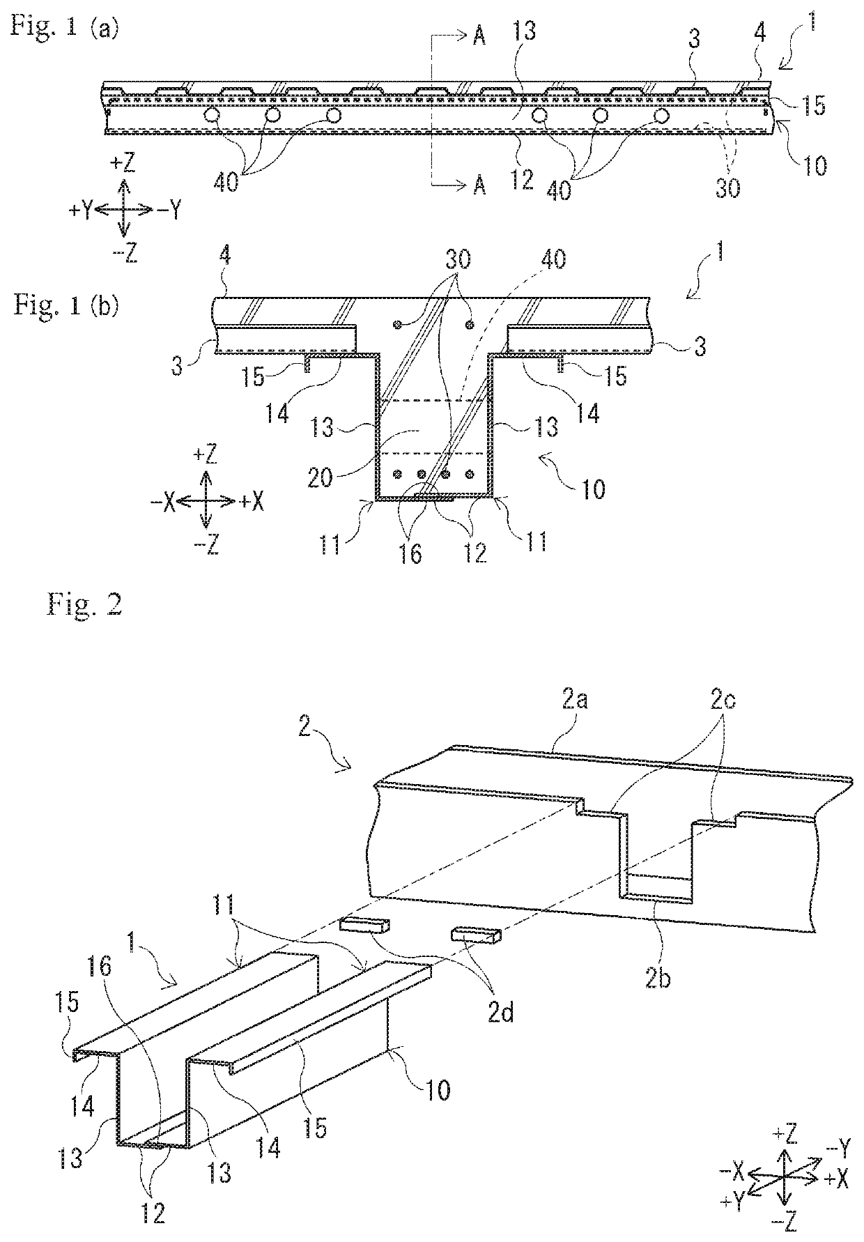
[0118]As described above, in the binding beam 1 of Embodiment 1, the binding beam concrete 20 has an outer shell covered by the steel form 10, and thus it is possible to suppress a decline in proof stress during the formation of the web opening 40 in the side surface of the binding beam 1 and it is possible to reduce the labor and cost entailed by separate reinforcing member attachment for forming the web opening 40.
[0119]In addition, it is possible to calculate a complex allowable bending moment and a complex allowable shear force taking the respective bearing ratios of the steel form 10 and the binding beam concrete 20 into account and it is possible to optimize the design of the binding beam 1.
[0120]Since the outer shell of the binding beam concrete 20 is covered by the steel form 10, the part where the web opening 40 can be formed is not limited to the part of reinforcing member attachment unlike in the related art. As a result, the degree of freedom of th...
embodiment 2
Effects of Embodiment 2
[0133]As described above, with the binding beam 50 of Embodiment 2, it is possible to form the web opening 40 simply by removing the cylindrical form 52. Accordingly, it is possible to simplify the work for forming the web opening 40 at a construction site.
modification examples regarding embodiments
[III] MODIFICATION EXAMPLES REGARDING EMBODIMENTS
[0134]The embodiments according to the invention have been described. However, the specific configurations and means of the invention can be modified and improved in any manner within the scope of the technical idea of each invention described in the claims. Such modification examples will be described below.
Regarding Problems to be Solved and Effects of Invention
[0135]First of all, the problems to be solved by the invention and the effects of the invention are not limited to the above and may vary with the details of the implementation environment and configuration of the invention, and only some of the problems described above may be solved and only some of the effects described above may be achieved in some cases.
[0136](Inter-Embodiment Relationship)
[0137]The features of each embodiment and the features according to each of the following modification examples may be mutually replaced or one feature may be added to another. For exam...
PUM
 Abstract
Description
Claims
Application Information