Force sensor protection mechanism, end effector, and robot arm

a technology of end effector and force sensor, which is applied in the direction of force/torque/work measurement apparatus, programme control, instruments, etc., can solve the problems of sensor constrained in a deformation, force sensor may break down, manufacturing error,

Active Publication Date: 2015-04-09
CANON KK
View PDF7 Cites 12 Cited by
  • Summary
  • Abstract
  • Description
  • Claims
  • Application Information

AI Technical Summary

Benefits of technology

[0009]The present invention provides a force sensor protection mechanism, and an end effector and robot arm having a force sensor protection mechanism that, when protecting a force sensor, do not restrict the operation of the force sensor by mechanical constraint so that an overload is not applied to the force sensor.

Problems solved by technology

However, since a force sensor is frail, the force sensor may break down when an overload is applied to the force sensor.
However, there is a limit, and a manufacturing error occurs.
If there is a manufacturing error in the active engaging member and the passive engaging member, the force sensor is constrained in a deformed state owing to the manufacturing error, and an overload continues to be applied to the force sensor.
If the force of engagement between the active engaging member and the passive engaging member is weakened, they do not function as a force sensor protection mechanism.

Method used


Image

  • Force sensor protection mechanism, end effector, and robot arm
  • Force sensor protection mechanism, end effector, and robot arm
  • Force sensor protection mechanism, end effector, and robot arm

Examples


first embodiment

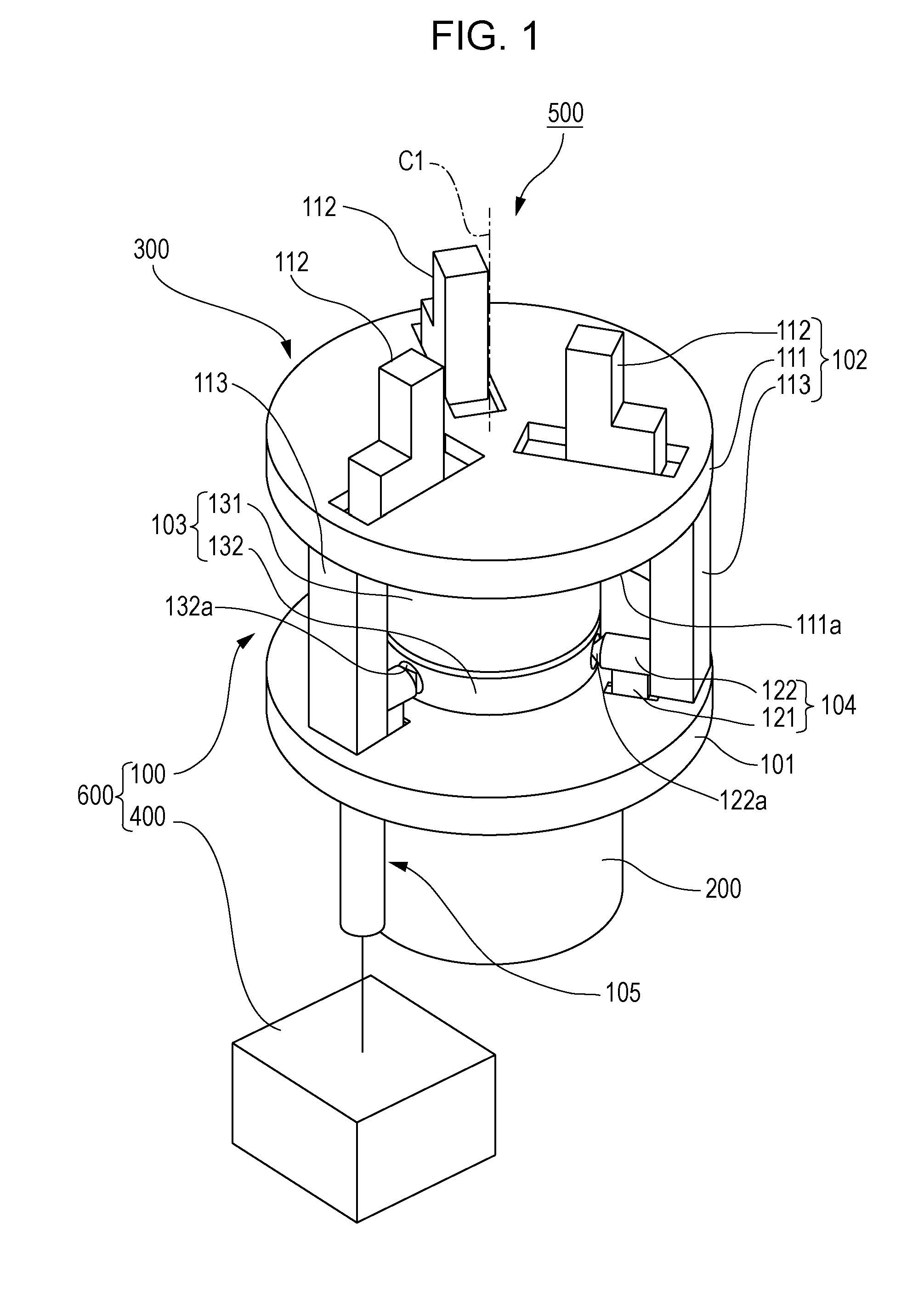
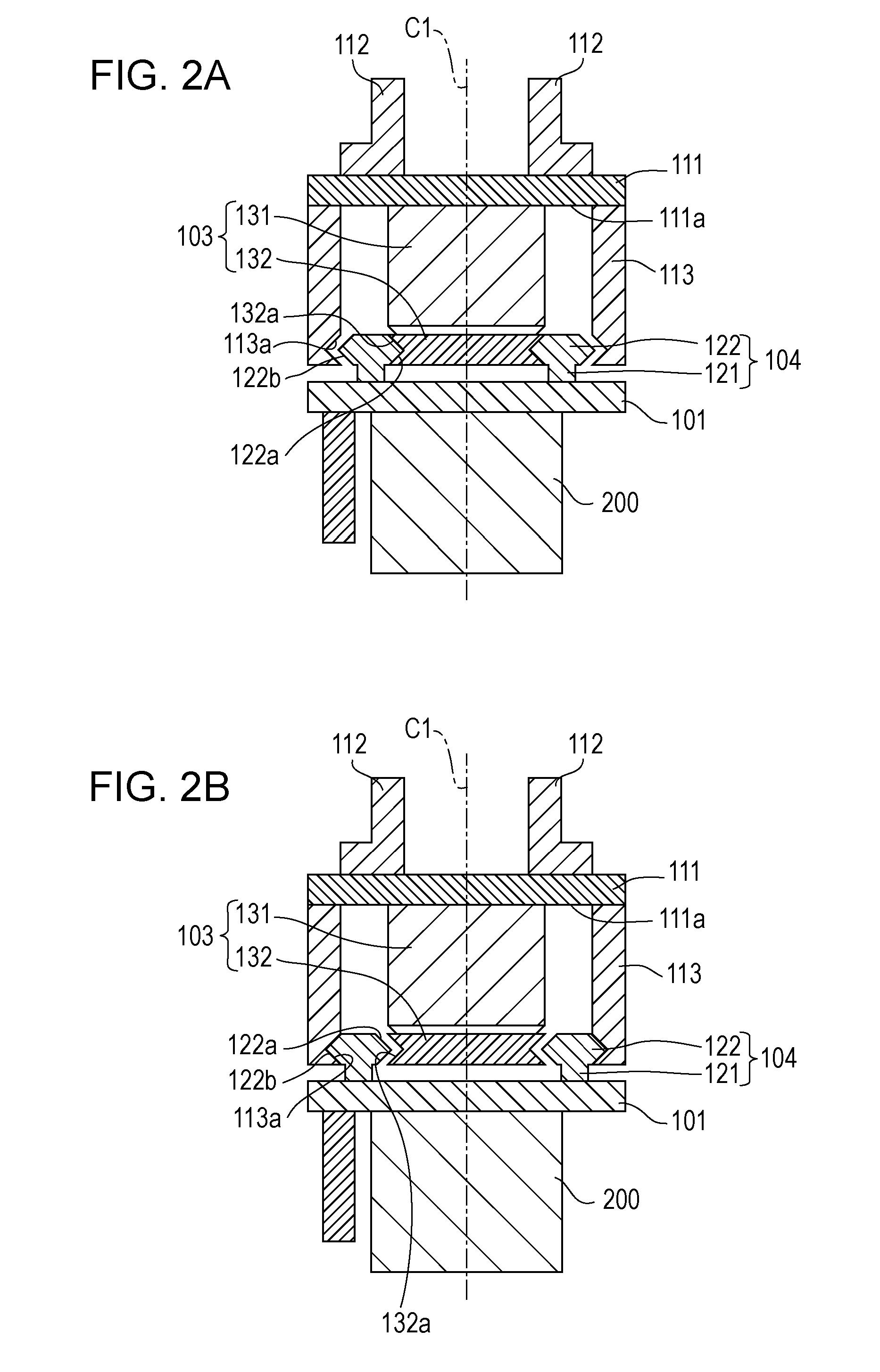
[0019]FIG. 1 is a perspective view showing the approximate configuration of a robot apparatus according to a first embodiment of the present invention. FIGS. 2A and 2B are sectional views showing the robot apparatus according to the first embodiment of the present invention. FIG. 2A shows a state where supporting members are moved to a first position. FIG. 2B shows a state where the supporting members are moved to a second position. FIG. 3 is a side view showing the robot apparatus according to the first embodiment of the present invention. FIGS. 4A and 4B are sectional views showing a force sensor protection mechanism. FIG. 4A is a sectional view taken along line IVA-IVA of FIG. 3. FIG. 4B is a sectional view taken along line IVB-IVB of FIG. 3.

[0020]As shown in FIG. 1, a robot apparatus 500 includes a multi-jointed robot arm 200, an end effector 300 having a force sensor protection mechanism 100, and a control device (control unit) 400 that controls the force sensor protection mech...

second embodiment

[0054]Next, a robot apparatus to which a force sensor protection mechanism according to a second embodiment of the present invention is applied will be described. FIGS. 5A and 5B are sectional views showing the robot apparatus according to the second embodiment of the present invention. FIG. 5A shows a state where supporting members are moved to a first position. FIG. 5B shows a state where the supporting members are moved to a second position. In the second embodiment, the same reference numerals will be used to designate the same components as those in the first embodiment, and the description thereof will be omitted.

[0055]In the first embodiment, a description has been given of a case where a driving unit has a rotary drive source, and rotational movement is converted into linear movement to move supporting members. In the second embodiment, a description will be given of a case where a driving unit has a linear drive source, and linear movement is converted into rotational movem...

third embodiment

[0070]Next, a robot apparatus to which a force sensor protection mechanism according to a third embodiment of the present invention is applied will be described. FIGS. 6A and 6B are sectional views showing the robot apparatus according to the third embodiment of the present invention. FIG. 6A shows a state where supporting members are moved to a first position. FIG. 6B shows a state where the supporting members are moved to a second position. In the third embodiment, the same reference numerals will be used to designate the same components as those in the first and second embodiments, and the description thereof will be omitted.

[0071]The robot apparatus 500B of the third embodiment includes a robot arm 200, an end effector 300B having a force sensor protection mechanism 100B, and a control device (not shown) that is substantially the same as the control device 400 of the first embodiment.

[0072]The end effector 300B is configured to be attachable to the distal end of the robot arm 20...


PUM

PropertyMeasurementUnit
forceaaaaaaaaaa
physical quantityaaaaaaaaaa
displacementaaaaaaaaaa

Abstract

An end effector base and a finger unit are formed as separate members, and are disposed with a space therebetween. A force sensor is fixed to a finger base of the finger unit, and is disposed with a space between it and the end effector base. Three supporting members are supported by the end effector base, and are configured to be able to be moved by the driving of a driving unit to a position where they support the force sensor and a position where they are separated from the force sensor and support the finger unit.

Description

BACKGROUND OF THE INVENTION[0001]1. Field of the Invention[0002]The present invention relates to a force sensor protection mechanism that protects a force sensor against an overload, an end effector having a force sensor protection mechanism, and a robot arm having a force sensor protection mechanism.[0003]2. Description of the Related Art[0004]In industrial robot apparatuses or the like, sometimes, a force sensor is installed between a robot arm and an end effector, force given to a work object by the end effector is detected, and work is performed while adjusting this force. In general, many force sensors calculate force acting on the force sensors on the basis of the change in physical quantity such as the stain of a member. In order to obtain high sensitivity to a weak force or a minute change, the sensitive member of a force sensor is reduced in rigidity, is made easily deformable, and is made frail so that the quantity of strain (the change in physical quantity) of the member ...

Claims


Application Information

Patent Timeline
Patent Type & Authority Applications(United States)
IPC IPC(8): G01L1/04B25J9/16
CPCB25J9/1633G01L1/04G01L5/226G01L5/0071B25J9/1612G05B2219/39496G05B2219/39528
Inventor ARAI, MASAYUKI
Owner CANON KK
Why Eureka
Try Eureka