Compensation for canonical second order systems for eliminating peaking at the natural frequency and increasing bandwidth

a second-order system and peaking technology, applied in the field of limiting resonance, can solve the problem that no prior art design teaches an algorithmic approach to resonance compensation, and achieve the effect of increasing bandwidth and reducing peaking

Active Publication Date: 2015-04-09
PAIGE NICHOLAS
View PDF5 Cites 6 Cited by
  • Summary
  • Abstract
  • Description
  • Claims
  • Application Information

AI Technical Summary

Benefits of technology

[0042]In a third aspect, the present invention is directed to a method of eliminating peaking and increasing bandwidth of a Fast Tool Servo system having a piezo actuator, a system frequency, and a mechanism frequency, the method comprising: forming a control loop for the resonant-prone system, the control loop including a forward path and a feedback path; adding gain into the forward path of the control loop of the system, wherein the gain added includes a function of the system and mechanism frequencies; and adding a phase lead or feedback factor (H-factor) into the feedback path of the control loop of the system, the phase lead being a complex ratio of the system and mechanism frequencies, wherein the Fast Tool Servo system is represented by a canonical second order system having the system frequency, and a resonant-prone mechanism having the mechanism frequency.

Problems solved by technology

(The “plant” is a preexisting system that does not meet all the desired frequency and time domain design specifications of the feedback system.)
None of the prior art designs teach an algorithmic approach to resonance compensation that does not include the deployment of extra filters, and instead strictly introduces gain and phase shifting as the only means of compensating for the resonant frequency.

Method used


Image

  • Compensation for canonical second order systems for eliminating peaking at the natural frequency and increasing bandwidth
  • Compensation for canonical second order systems for eliminating peaking at the natural frequency and increasing bandwidth
  • Compensation for canonical second order systems for eliminating peaking at the natural frequency and increasing bandwidth

Examples


Embodiment Construction

)

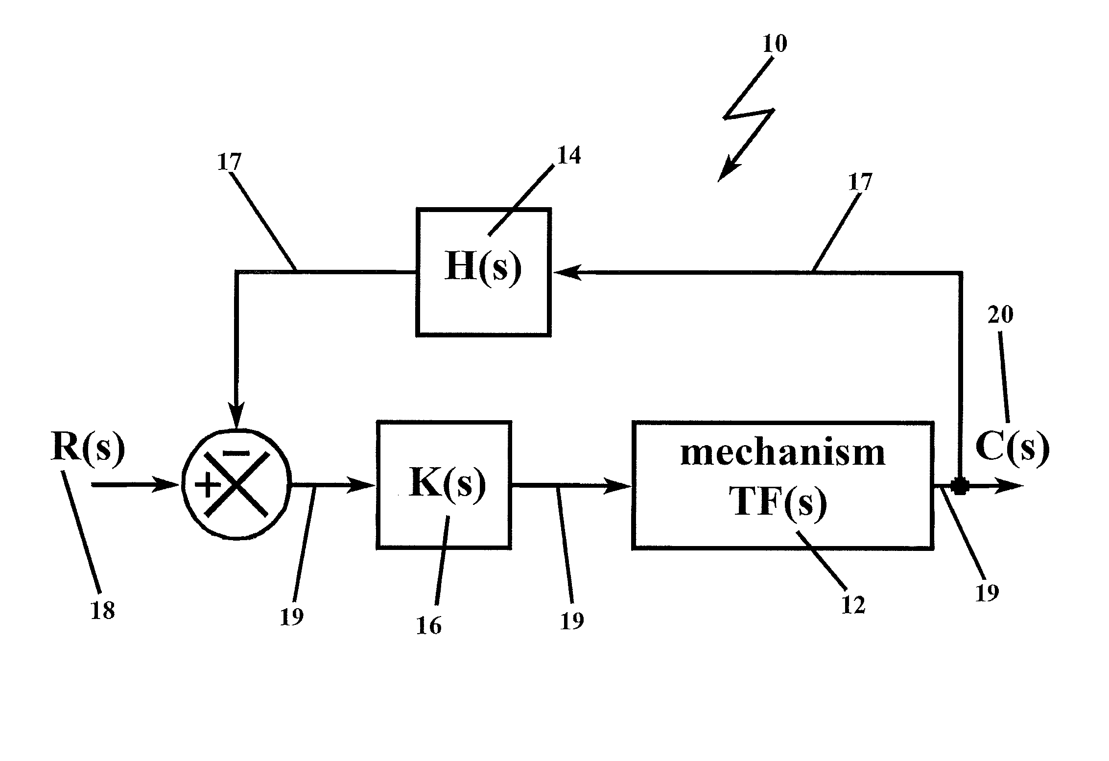
[0070]In describing the preferred embodiment of the present invention, reference will be made herein to FIGS. 1-22 of the drawings in which like numerals refer to like features of the invention.

[0071]The methodology of the present invention solves the problem of unwanted resonance in resonance-prone systems. The prior art has gone to great lengths to remove the resonance altogether, employing notch filters at frequencies identical to the resonance frequency to remove selectively the resonance frequency entirely from the circuit function, and / or low-pass filter systems that allow frequencies up to the resonance frequency to pass, but cutoff frequencies that are higher than the low-pass filter bandwidth, and high-pass filter systems that allow frequencies below the high-pass filter bandwidth to be cutoff.

[0072]Counter-intuitive to the operative solutions of the prior art, the present invention adds an analytically derived, predetermined gain to the loop that effectively functions to ...


PUM


Abstract

The present invention adds gain and phase into a canonical second order system in order to mitigate the adverse effects of unwanted resonance, where the gain is added to the forward path of a control loop of the system and is a ratio of the square of the system and mechanism frequencies, and the phase lead (H-factor) is added to the feedback path of the control loop of the system and is a complex ratio of these frequencies which includes a dc-component (Hdc) and a zero- or pole-component. By adding gain and phase lead, which is contrary to current approaches to addressing resonance, the present invention achieves the desired result of resonant free application in a canonical resonant-prone system of second order, and the methodology is applicable to higher order systems.

Description

BACKGROUND OF THE INVENTION[0001]1. Field of the Invention[0002]The present invention relates to a method for limiting resonance, that is, eliminating peaking at a system's natural frequency, especially in electronic circuits, although the methodology may be applied to other oscillating systems as well, such as mechanical systems (spring mass systems, torque-inertia systems), piezoelectric transducer systems, and clamped systems, to name a few. The prior art addresses the resonance problem by filtering; essentially, operating at frequencies above or below the resonant frequency, but not at the resonant frequency. The present invention allows a system to operate through its resonant frequency without filtering by strictly introducing gain and phase shifting as the only means of compensating for the resonant frequency. In this manner, the present invention also increases the operating bandwidth of the system.[0003]2. Description of Related ArtBackground Theory[0004]Resonance is the te...

Claims


Application Information

Patent Timeline
Patent Type & Authority Applications(United States)
IPC IPC(8): G01Q30/00G01Q60/10
CPCG01Q60/10G01Q30/00G05B5/01
Inventor PAIGE, NICHOLASHOOGSTRATE, JR., JOHN R.
Owner PAIGE NICHOLAS
Why Eureka
Try Eureka