Shaft assembly with Anti-pull apart stake

a technology of anti-pull-apart and shaft assembly, which is applied in the direction of couplings, manufacturing tools, transportation and packaging, etc., can solve the problems of preventing the achievement of a required minimum pull-apart load, and achieve the effect of facilitating interference and interference fi

Active Publication Date: 2015-04-16
STEERING SOLUTIONS IP HLDG
View PDF9 Cites 5 Cited by
  • Summary
  • Abstract
  • Description
  • Claims
  • Application Information

AI Technical Summary

Benefits of technology

[0006]In accordance with another exemplary embodiment of the invention, a steering shaft assembly is provided. The assembly includes a first shaft having a first end, a second end, and a splined outer surface. A tubular second shaft includes a first end, a second end having an end surface, and a splined inner surface. The second shaft second end receives the first shaft first end along a longitudinal axis of the second shaft. At least one stake extends axially into the second shaft end surface. The at least one stake is configured to deform at least a portion of the splined inner surface to facilitate an interference fit between the first and second shafts and configured to resist a predetermined axial separation load being applied to the first and second shafts.
[0007]In accordance with yet another exemplary embodiment of the invention, a method of manufacturing a shaft coupling is provided. The method includes providing a first shaft having a splined outer surface, providing a tubular second shaft having an end surface and a splined inner surface, the second shaft receiving the first shaft along a longitudinal axis of the second shaft, and providing a die pot having at least one pin. The method further includes disposing the first and second shafts in the die pot such that the at least one pin is oriented against the second shaft end surface, and forcing the at least one pin into the second shaft end surface to form at least one stake extending axially into the second shaft end surface. The at least one stake is configured to deform at least a portion of the splined inner surface to facilitate an interference fit between the first and second shafts preventing axial removal of first shaft from second shaft until a predetermined axial load is applied to the first and second shafts.

Problems solved by technology

However, with some assemblies, angled stakes may create an interference condition that causes high stroke efforts and undesired drag, thereby preventing achievement of a required minimum pull-apart load.

Method used


Image

  • Shaft assembly with Anti-pull apart stake
  • Shaft assembly with Anti-pull apart stake
  • Shaft assembly with Anti-pull apart stake

Examples


Embodiment Construction

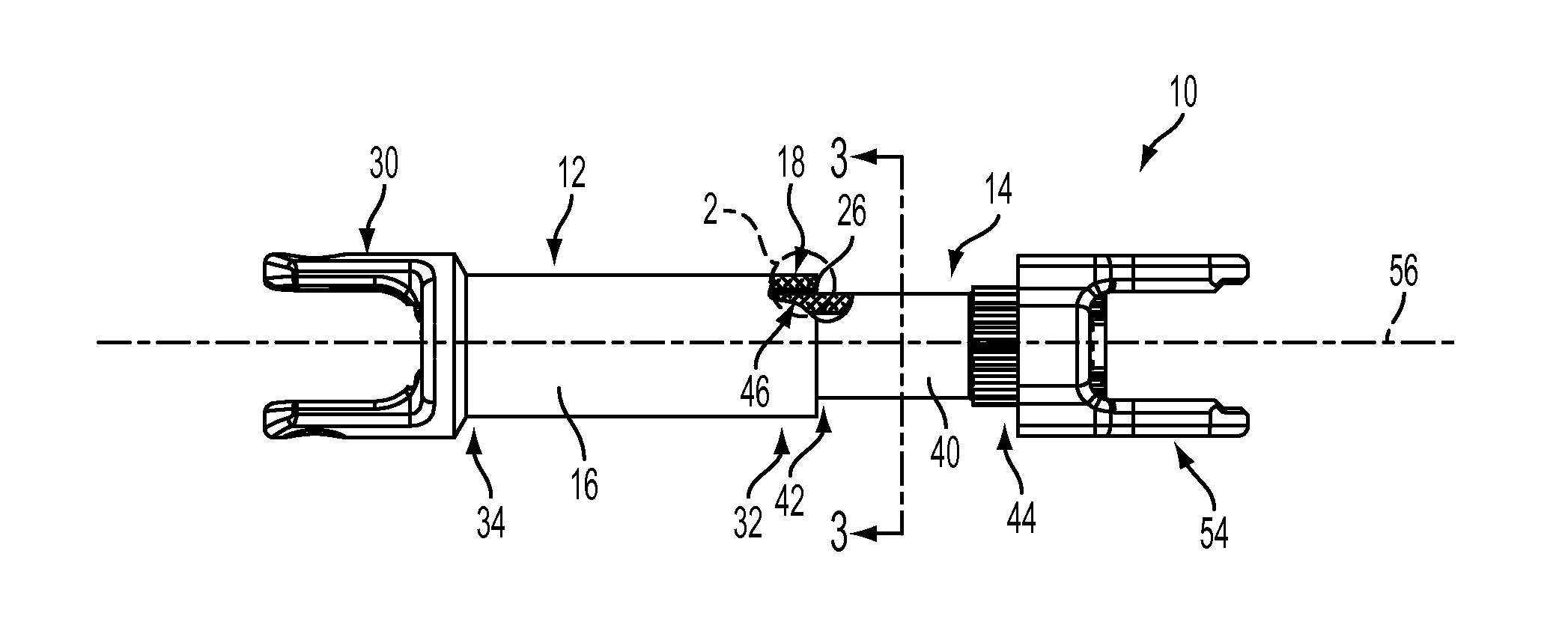
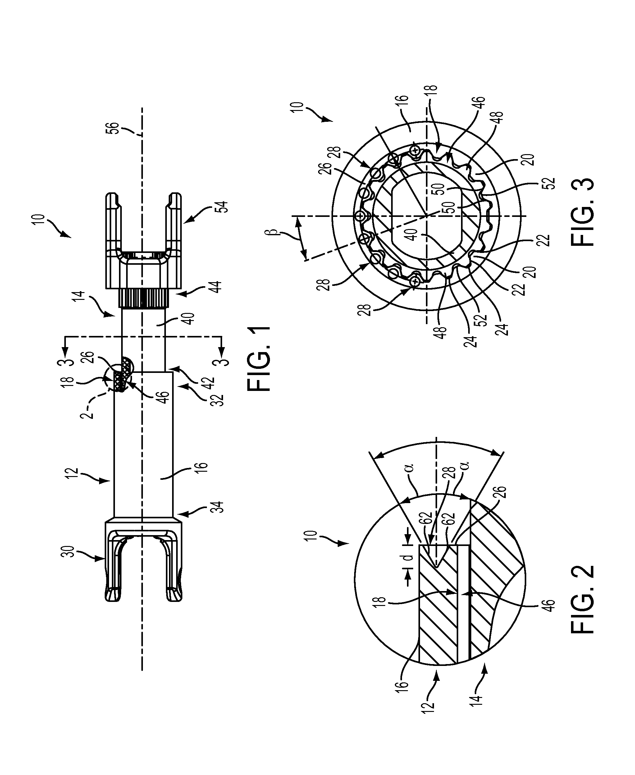
[0016]Referring now to the Figures, where the invention will be described with reference to specific embodiments, without limiting same, FIGS. 1-3 illustrate an exemplary shaft assembly 10. In the exemplary embodiment, assembly 10 is a steering column shaft assembly that includes a first shaft section 12 and a second shaft section 14 sliding disposed within first shaft section 12. However, assembly 10 may be any type of suitable shaft assembly.

[0017]First shaft section 12 includes a tubular shaft body 16 having a first end 32, a second end 34, and a splined section 18 formed on the inner surface or diameter of tubular shaft body 16. Splined section 18 is configured to engage second shaft section 14 and includes a plurality of teeth 20 defined by tapered surfaces 22 and involute surfaces 24 (FIG. 3). Alternatively, surfaces 24 may be straight sided. Shaft first end 32 includes an end surface 26 having a plurality of stakes 28 formed therein, as is described herein in more detail. Sha...


PUM

PropertyMeasurementUnit
angleaaaaaaaaaa
angleaaaaaaaaaa
angleaaaaaaaaaa

Abstract

In accordance with an exemplary embodiment of the invention, a shaft coupling is provided. The shaft coupling comprises a first shaft having a splined outer surface, a tubular second shaft having an end surface and a splined inner surface, the second shaft receiving the first shaft along a longitudinal axis of the second shaft, and at least one stake extending axially into the second shaft end surface. The at least one stake deforms at least a portion of the splined inner surface to facilitate an interference fit between the first and second shafts and configured to resist a predetermined axial separation load being applied to the first and second shafts.

Description

CROSS REFERENCE TO RELATED APPLICATION[0001]This application claims the benefit of U.S. Provisional Application Ser. No. 61 / 889,726, filed Oct. 11, 2013, the contents of which are incorporated herein by reference thereto.BACKGROUND OF THE INVENTION[0002]The following description relates to shaft assemblies, and more particularly, to a steering column assembly with anti-pull apart features.[0003]In some known tubular shaft assemblies having two or more shafts, angled stakes are formed on the outer diameter of one tubular shaft to prevent another shaft being removed from the tubular shaft. However, with some assemblies, angled stakes may create an interference condition that causes high stroke efforts and undesired drag, thereby preventing achievement of a required minimum pull-apart load.[0004]Accordingly, it is desirable to provide a steering column assembly that both achieves the minimum pull-apart load and prevents an undesired interference between two shafts.SUMMARY OF THE INVENT...

Claims


Application Information

Patent Timeline
Patent Type & Authority Applications(United States)
IPC IPC(8): F16D1/027B62D1/185
CPCF16D1/027B62D1/185F16D1/04B62D1/16B62D1/20F16D1/0858F16D2300/12Y10T29/49908Y10T403/4933
Inventor VASICEK, MATTHEW D.WYNN, BRANDON G.SCHULTZ, ZACHERY P.MATOUSEK, DAVID G.
Owner STEERING SOLUTIONS IP HLDG
Why Eureka
Try Eureka