Intelligent Door Lock System that Minimizes Inertia Applied to Components

a door lock and component technology, applied in the field of intelligent door lock systems, can solve the problems of unauthorized entry, theft, easy improper depressing of latches by themselves, etc., and achieve the effects of wide temperature independence, low power consumption, and wide temperature independen

Active Publication Date: 2015-04-16
AUGUST HOME
View PDF3 Cites 67 Cited by
  • Summary
  • Abstract
  • Description
  • Claims
  • Application Information

AI Technical Summary

Benefits of technology

[0012]Another object of the present invention is to provide an intelligent door lock system that has battery voltage and chemistry independence.
[0013]Yet another object of the present invention is to provide an intelligent door lock system that has wider temperature independence.
[0014]Still another object of the present invention is to provide an intelligent door lock system that has wider temperature independence, while functioning substantially the same irrespective of energy source (battery) and temperature situations, subject to non-operation and very low power and very high or low temperatures.
[0015]Another object of the present invention is to provide an intelligent door lock system that has a nicer appearance and better sound because the motor doesn't labor.

Problems solved by technology

Such a latch by itself is often easy to improperly depress-release by an unauthorized person, with a card-type element or even a pry bar.
However, if a person forgets to so actuate the deadbolt, either manually with an inner hand turn when inside, or by a key outside, an intruder need only inactivate the latch mechanism in order to gain unauthorized entry.
Motel and hotel rooms often do not even have a key actuated deadbolt and thus are particularly susceptible to unauthorized entry and theft when the person is not in the room.

Method used


Image

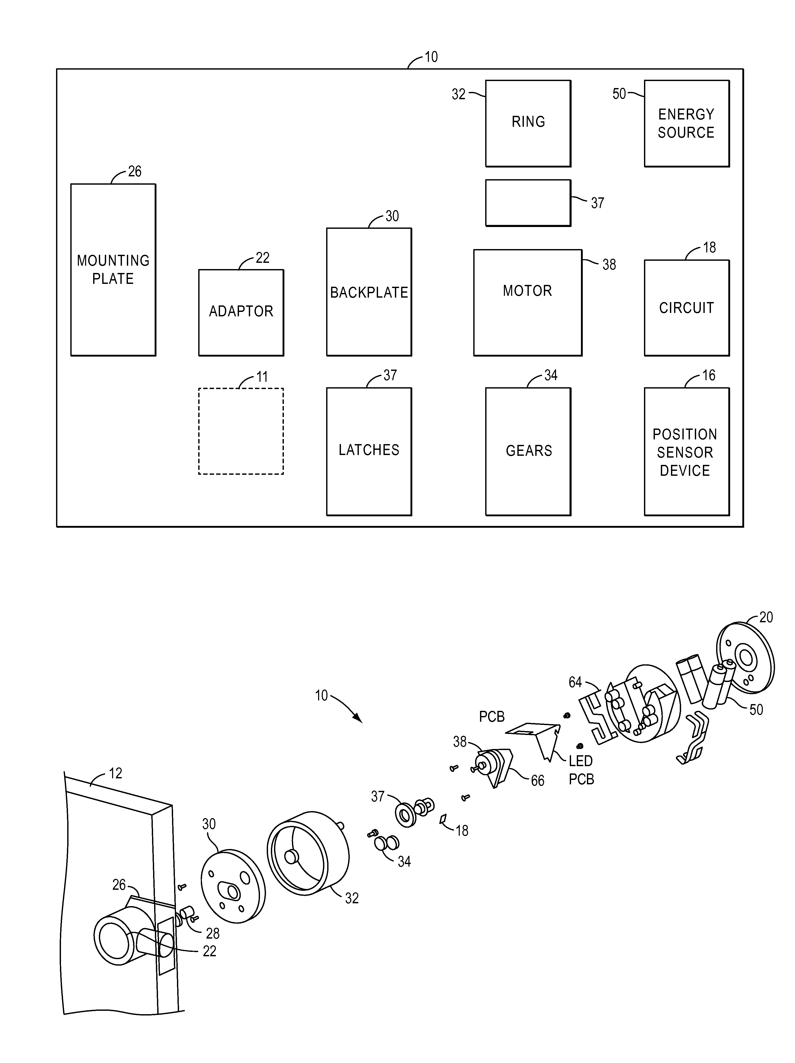
  • Intelligent Door Lock System that Minimizes Inertia Applied to Components
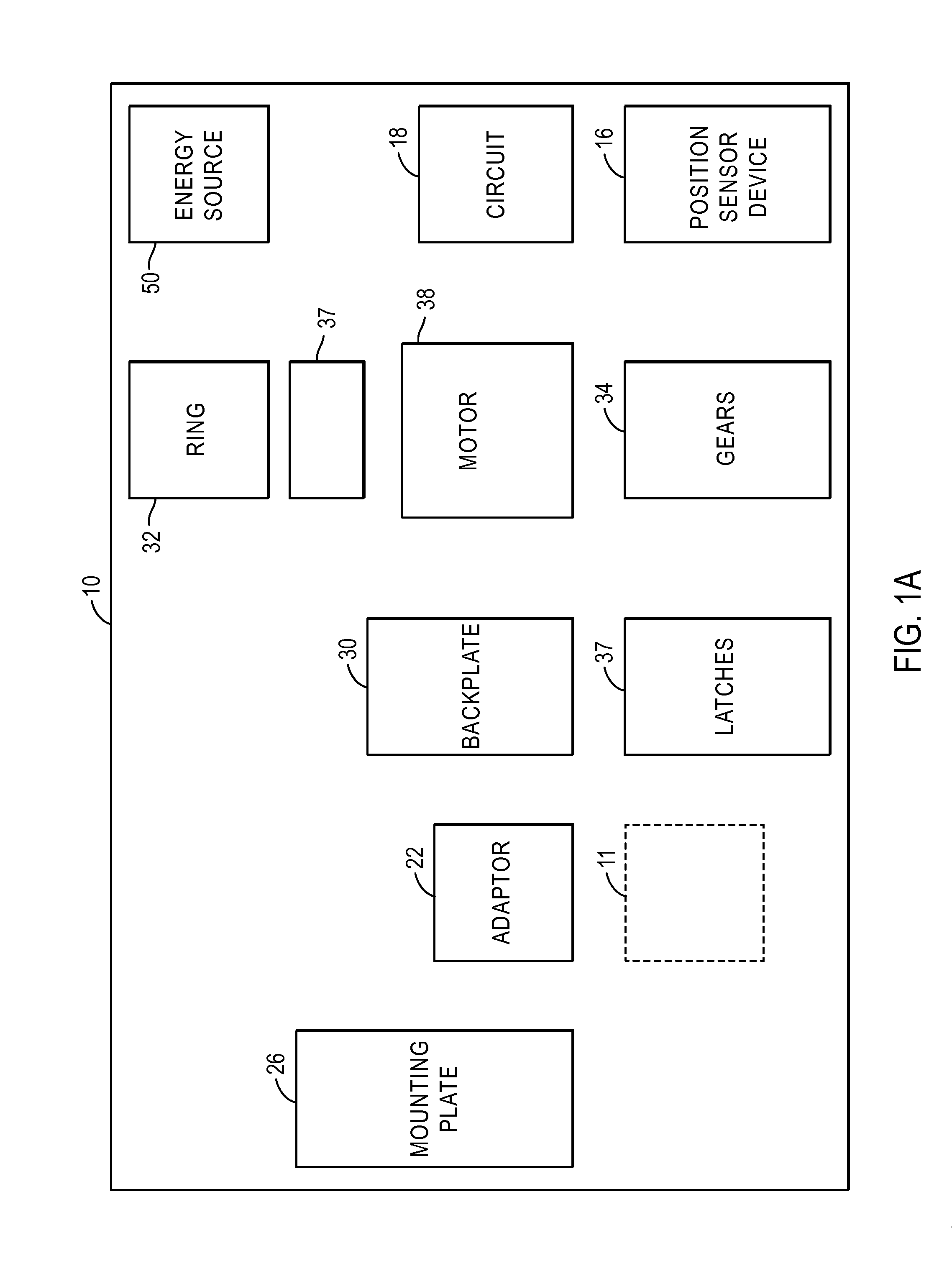
  • Intelligent Door Lock System that Minimizes Inertia Applied to Components
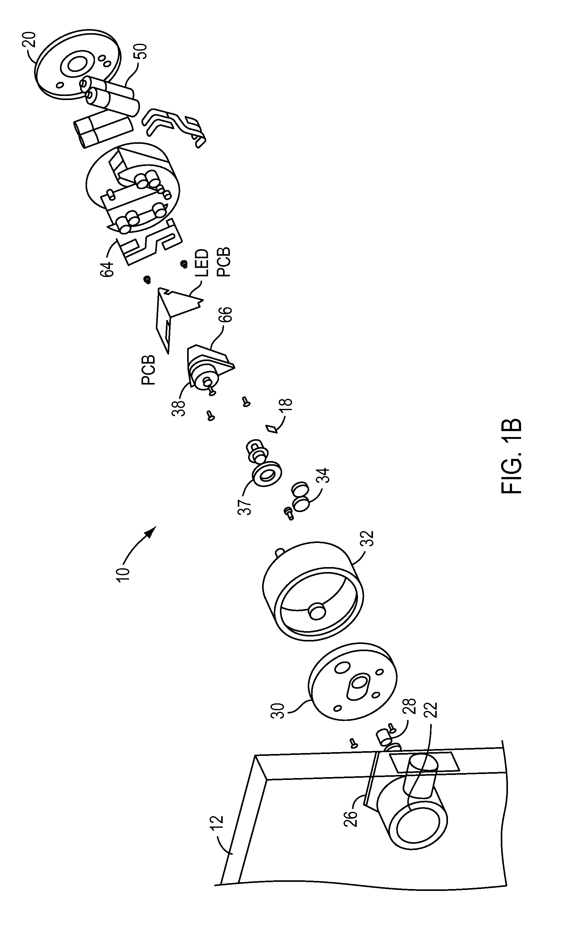
  • Intelligent Door Lock System that Minimizes Inertia Applied to Components

Examples


Embodiment Construction

[0056]As used herein, the term engine refers to software, firmware, hardware, or other component that can be used to effectuate a purpose. The engine will typically include software instructions that are stored in non-volatile memory (also referred to as secondary memory). When the software instructions are executed, at least a subset of the software instructions can be loaded into memory (also referred to as primary memory) by a processor. The processor then executes the software instructions in memory. The processor may be a shared processor, a dedicated processor, or a combination of shared or dedicated processors. A typical program will include calls to hardware components (such as I / O devices), which typically requires the execution of drivers. The drivers may or may not be considered part of the engine, but the distinction is not critical.

[0057]As used herein, the term database is used broadly to include any known or convenient means for storing data, whether centralized or di...


PUM


Abstract

An intelligent door lock system includes components, a drive shaft of a lock device, a processor coupled to a wireless communication device, and an energy source coupled to a circuit. A device that converts energy into mechanical energy is coupled to the circuit and the drive shaft. The device that converts energy is coupled to the energy source to receive energy from the energy source. A ramp-up speed, a steady state speed and a ramp down speed are applied to the device that converts energy into mechanical energy. The ramp-up speed is applied when a first component initially engages with a second component. The steady state speed is applied following the initial engagement and is an operational speed that the device which converts energy uses during a standard operation mode. The ramp down speed is applied as the first and second components begin a state of non-engagement.

Description

CROSS-REFERENCE TO RELATED APPLICATIONS[0001]The present application claims priority to U.S. Provisional Patent Application Ser. No. 62 / 036,979, filed Aug. 13, 2014; U.S. Provisional Patent Application No. 62 / 036,971, filed Aug. 13, 2014; U.S. Provisional Patent Application No. 62 / 036,991, filed Aug. 13, 2014, U.S. Provisional Patent Application No. 62 / 036,993, filed Aug. 13, 2014 and U.S. Provisional Patent Application No. 62 / 036,989, filed Aug. 13, 2014, the entire contents of which applications are incorporated by reference as set forth herein.BACKGROUND[0002]1. Field of the Invention[0003]The present invention relates to intelligent door lock systems, and more particularly to, intelligent door lock systems that minimize inertia have a ramp up speed, steady state speed and a ramp down speed for a motor to lock and unlock a door.[0004]2. Description of the Related Art[0005]Door lock assemblies often include deadbolts. Typically such an assembly included a latch which is depressed ...

Claims


Application Information

Patent Timeline
Patent Type & Authority Applications(United States)
IPC IPC(8): E05B47/00
CPCE05B47/0001E05B17/10E05B1/0007E05B47/0012E05B47/02E05B2047/002E05B2047/0058E05B2047/0091G07C9/00174G07C2009/00746G07C2009/00769Y10T292/1021
Inventor JOHNSON, JASONCHENG, SHIH YU THOMASMAINWARING, KUY N.
Owner AUGUST HOME
Why Eureka
Try Eureka