Light control system, light control method and computer readable memory

a technology of light control system and computer readable memory, applied in the direction of lighting equipment, lighting sources, electrical equipment, etc., can solve the problem of insufficient power saving

Active Publication Date: 2015-04-16
MEGACHIPS
View PDF2 Cites 12 Cited by
  • Summary
  • Abstract
  • Description
  • Claims
  • Application Information

AI Technical Summary

Benefits of technology

[0019]The present invention can perform light control on each lighting fixture without installing an illuminance sensor per seat.
[0020]These and other objects, features, aspects an...

Problems solved by technology

In such rooms, in control of the lighting equipment for efficient illumination suitable for occupancy status...

Method used


Image

  • Light control system, light control method and computer readable memory
  • Light control system, light control method and computer readable memory
  • Light control system, light control method and computer readable memory

Examples


first embodiment

1. First Embodiment

[0048][1-1. Configuration]

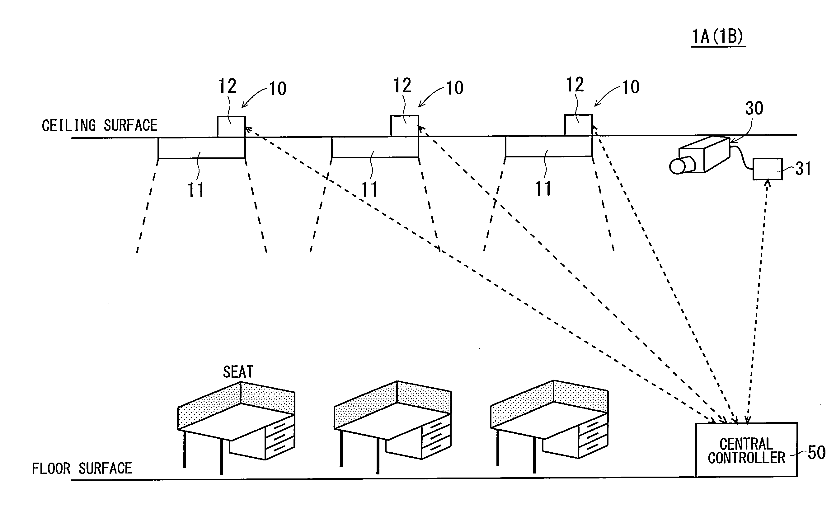
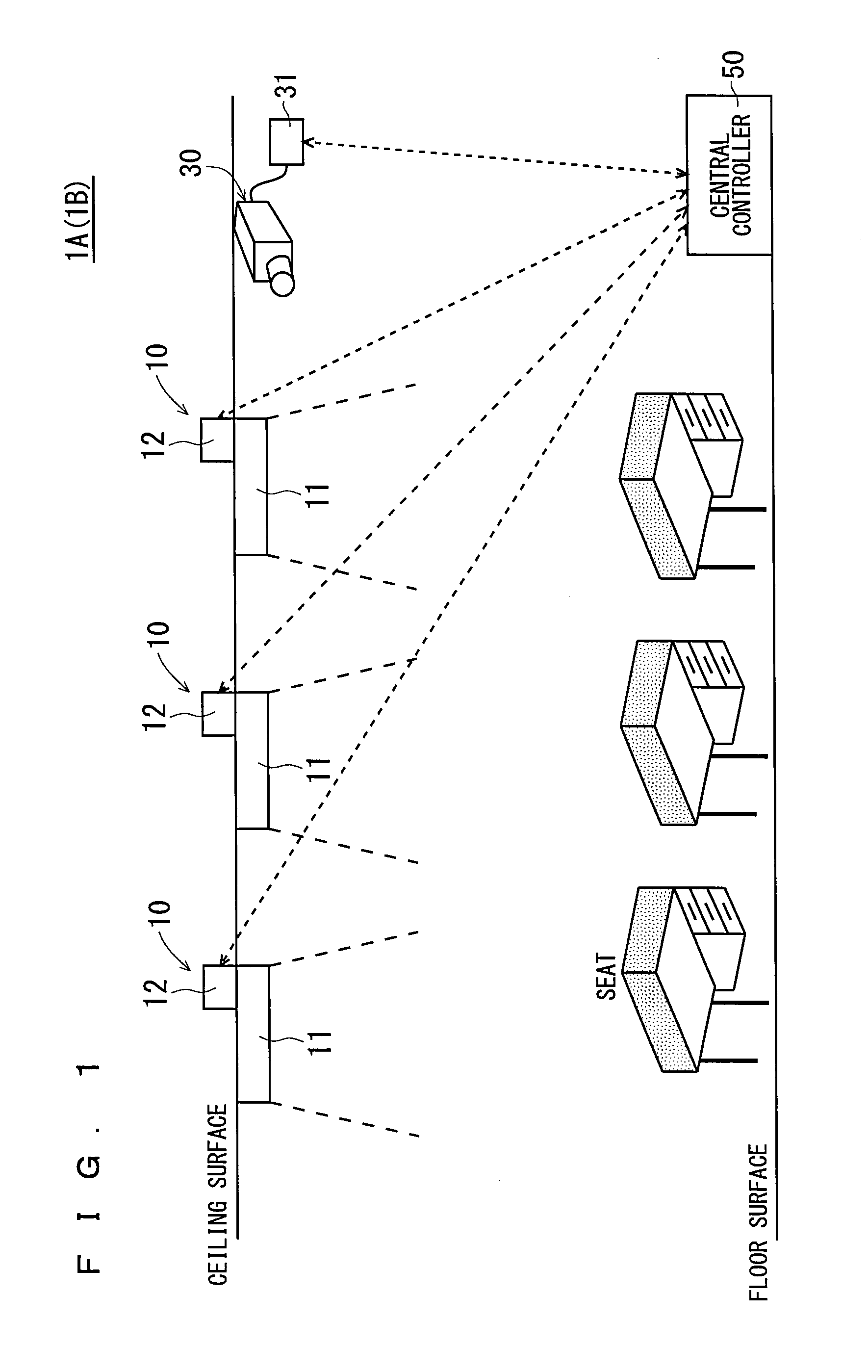
[0049]FIG. 1 is a view showing the overall configuration of a light control system 1A according to a first embodiment.

[0050]As shown in FIG. 1, the light control system 1A is configured with a plurality of lighting devices 10 provided on the ceiling of, for example, an office, a motion sensor 30, and a central controller 50.

[0051]The light control system 1A with the above-mentioned configuration performs a light control operation of detecting an occupancy status of each seat with the motion sensor 30 to perform light control on each of the lighting devices 10 with a central controller 50 based on the detected occupancy status.

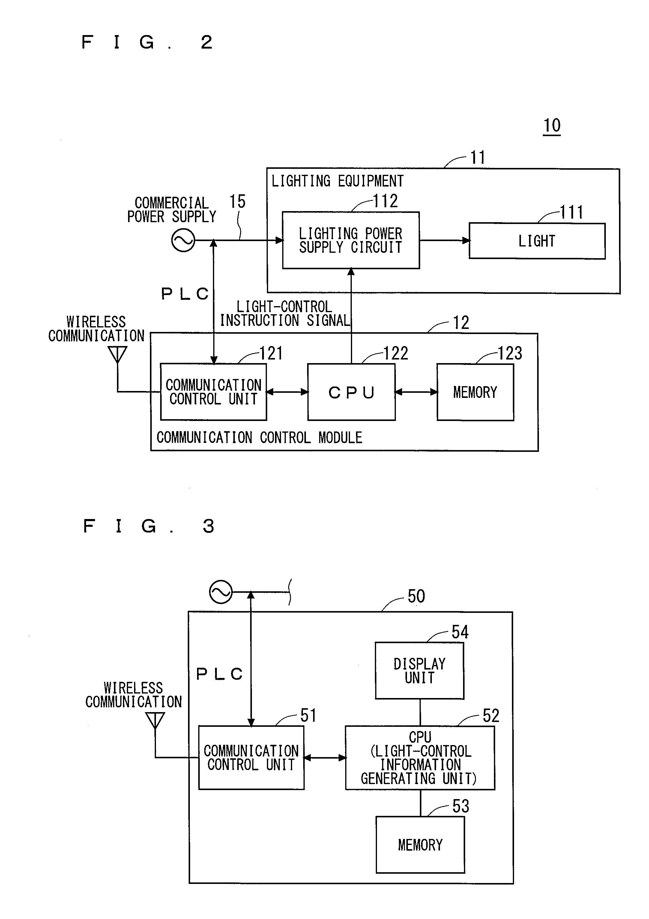
[0052]Each of the components of the light control system 1A will be described below in detail. FIG. 2 is a diagram showing the configuration of the lighting device 10. FIG. 3 is a diagram showing the configuration of the central controller 50.

[0053]As shown in FIG. 2, the lighting device 10 is configured with a light...

second embodiment

2. Second Embodiment

[0162]Next, a second embodiment of the present invention will be described. The light control system 1A according to the first embodiment does not take into account, in the calculation of an illuminance on a working surface at a grid point being a grid point of interest, the effects of light sources at grid points which are positioned with one grid point sandwiched between the grid point of interest and themselves. Meanwhile, a light control system 1B according to the second embodiment takes into account, in the calculation of an illuminance on a working surface at a grid point of interest, the effects of light sources at grid points which are positioned with one grid point sandwiched between the grid point of interest and themselves, on specific conditions. The light control system 1B has the structure and function almost identical to those of the light control system 1A (see FIGS. 1 to 3), and accordingly, the similar parts will be denoted by the same reference...


PUM


Abstract

A plurality of lighting devices are respectively arranged, on a ceiling surface, at a plurality of grid points of the ceiling surface partitioned in a grid pattern. A detection unit detects occupancy statuses of a plurality of seats located correspondingly to positions of the plurality of grid points. A controller is capable of communicating with each of the plurality of lighting devices. The controller includes a light-control information generating unit that regards a block formed of a plurality of grid points centering around a grid point of an occupied location as one group to generate, for each of groups set correspondingly to occupied locations, light control information on a lighting device that becomes a dimming target in the group. The controller also includes a transmission unit that transmits the light control information. The lighting device being a dimming target among the plurality of lighting devices performs light control based on the received light control information.

Description

TECHNICAL FIELD[0001]The present invention relates to a light control technology for lighting equipment.BACKGROUND ART[0002]In rooms of offices, schools, or the like, a large number of lighting equipment typically having a straight tube shape are arranged at regular intervals in a grid pattern on the ceiling.[0003]In such rooms, in control of the lighting equipment for efficient illumination suitable for occupancy statuses, power cannot be saved satisfactorily by merely turning off the lighting equipment near the seats of absentees.[0004]In rooms of offices or the like, the illuminance necessary for an occupant is obtained not only from the light of one piece of lighting fixture but also from the overlapped light of a plurality of lighting equipment. When turning off a lighting fixture, accordingly, not only its influence on the seat positioned directly below this lighting fixture but also its influence on the adjacent seats is preferably taken into account.[0005]For efficient illum...

Claims


Application Information

Patent Timeline
IPC IPC(8): H05B37/02
CPCH05B37/0227H05B37/0272H05B37/0263H05B47/19Y02B20/40H05B47/115H05B47/125H05B47/185
Inventor ASAMI, TOMONOBU
Owner MEGACHIPS
Why Eureka
Try Eureka