

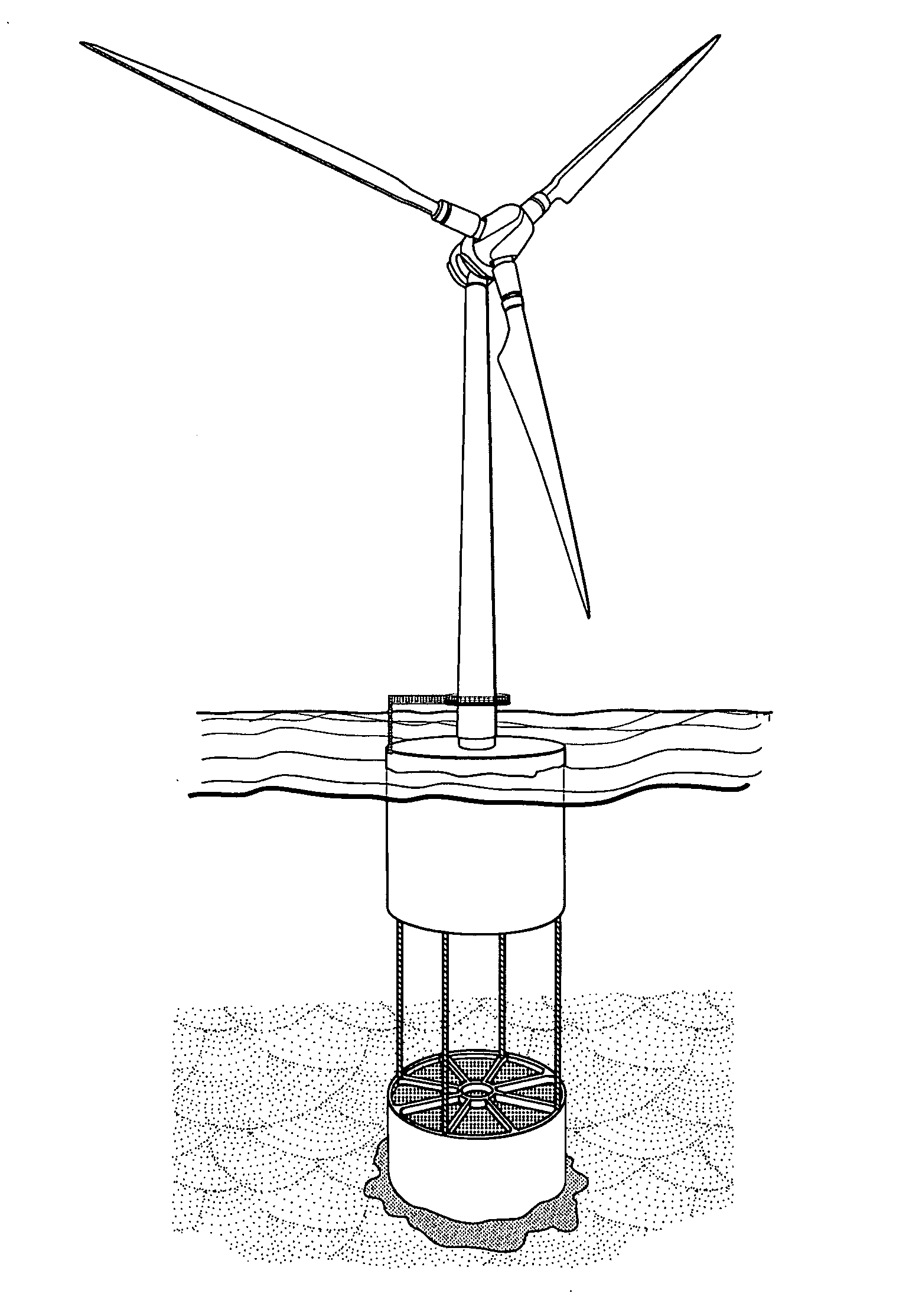
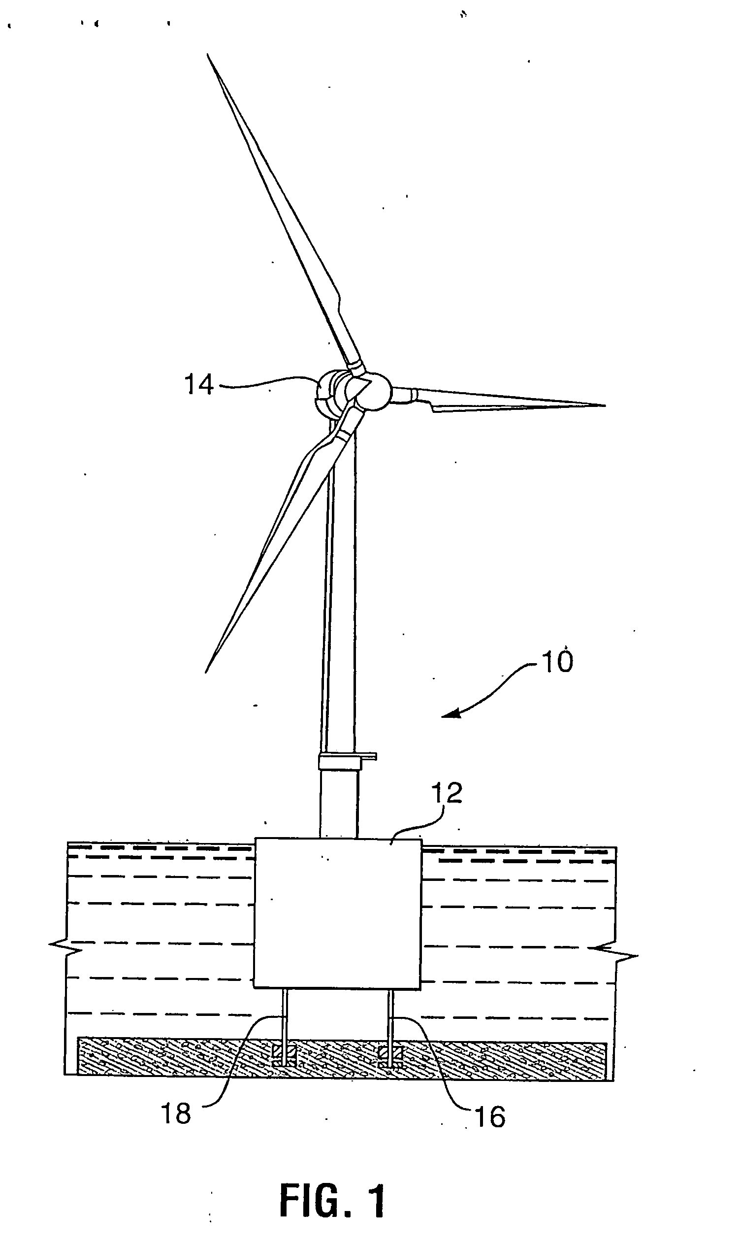
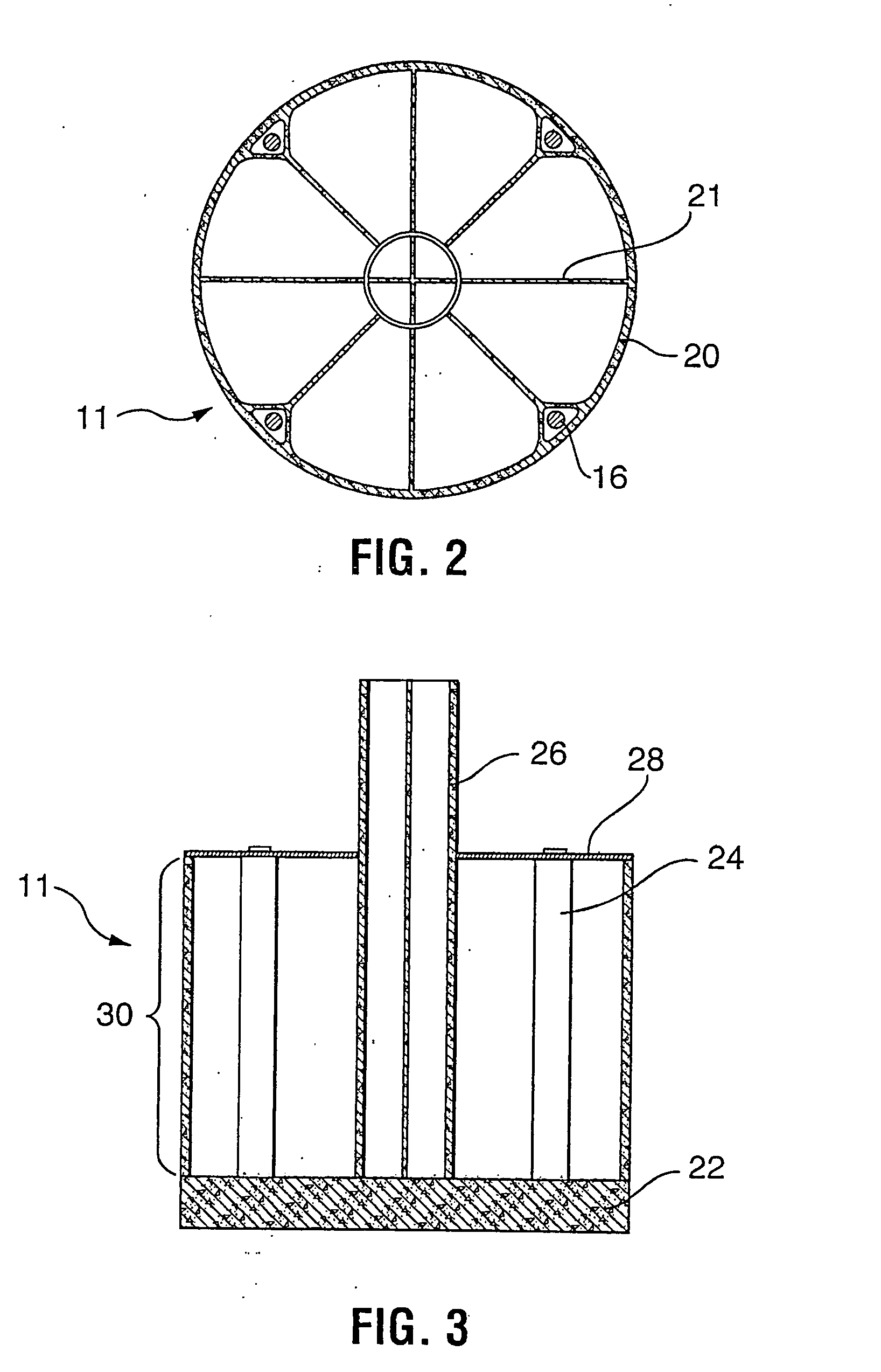
Method of construction, installation, and deployment of an offshore wind turbine on a concrete tension leg platform
a technology of offshore wind turbines and tension legs, which is applied in the direction of anchors, caissons, constructions, etc., can solve the problems of few if any being able to survive the loss of tension legs, limited or no sites for utility scale wind or solar power installations, and affecting the well-being of the wtg, etc., to facilitate the construction and installation of a spar buoy foundation
- Summary
- Abstract
- Description
- Claims
- Application Information
AI Technical Summary
Benefits of technology
Problems solved by technology
Method used
Image

Examples
case # 1
[0080]Requisite calculations are necessary to show the effect of these loads for the following cases:[0081]Case #1—The foundation in the trough of a 50 ft. wave in 300 ft. water with maximum wind, wave and current loads with wind normal to a square tension leg pattern.[0082]Case #2—The foundation in the trough of a 50 ft. wave in 300 ft. water with a maximum wind, wave and current loads with wind normal to a diamond tension leg pattern.
[0083]From the above calculations, the maximum and minimum tension leg loads are determined for each case. The minimum forces occur when the foundation is in the trough of the largest wave and the maximum forces occur when the foundation is in the crest of the largest wave. From this, the maximum external loads, with lateral and, thus, vertical displacement, do not slacken a tension leg. In the event of the failure of a pair of tendons, at the operating draft of 88 ft, the WTG / WTG foundation remains upright and stable and can withstand an up-setting m...
PUM
 Abstract
Description
Claims
Application Information