Supercharge Your Innovation With Domain-Expert AI Agents!

Inner-rotor-type motor

a technology of inner rotor and motor, which is applied in the direction of dynamo-electric machines, electrical apparatus, supports/encloses/casings, etc., can solve the problems of increasing the processing cost of components and the difficulty of assembly, and achieves the effect of saving material costs, improving assembly efficiency, and simple configuration

Active Publication Date: 2015-04-23
NIDEC SERVO CORP
View PDF4 Cites 2 Cited by
  • Summary
  • Abstract
  • Description
  • Claims
  • Application Information

AI Technical Summary

Benefits of technology

[0010]Preferred embodiments of the present invention provide an inner-rotor-type motor which makes it possible to easily and cost-effectively manufacture a cover member without impairing the dust-free interior of the motor and which enjoys a greatly improved ease of assembly.
[0016]In the inner-rotor-type motor configured as described above, four outer surface portions flush or substantially flush with the motor outer surface of the core-back portion are defined in the frame portion of each of the two insulating members of the insulator to secure insulation between the stator core and the coil. The outer surface portions of the frame portion of each of the insulating members are inserted between the leg portions of four corners of each of the cover members attached to the axial opposite sides of the stator core. In this state, the cover members are attached to the stator core. Therefore, each of the cover members is simple in configuration by provided the end plate portion and the leg portions arranged at the four corners. It is also possible to save the material costs and to form each of the cover members into a 90° rotation symmetry shape. Thus, the installation position of each of the cover members with respect to the stator has no directivity. Each of the cover members can be attached to the stator in any of the positions spaced apart 90° from each other. That is to say, there is no restriction in the fixing position of each of the cover members. This provides an advantage in that the ease of assembly is significantly improved.
[0017]In addition, each of the cover members has a simple shape in which the leg portions are merely arranged in the four corners. The frame portion of each of the insulating members is partially inserted between the leg portions to define the motor outer surface. Therefore, a dust-free interior of the motor is reliably secured. Moreover, the outer surface portions, i.e., some portions, of each of the insulating members are exposed to the outside. As a result, it is possible significantly enhance the design as compared with the conventional motor in which only the cover members are exposed to the outside.

Problems solved by technology

This leads to an increase in the component processing cost.
This poses a problem in that the assembly becomes difficult.
While the foregoing description has been made by taking an instance where the motor employs a hybrid type rotor, the aforementioned problems are also posed in an inner-rotor-type motor that employs, as its rotor, a permanent magnet type rotor in which different magnetic poles are alternately arranged along a circumferential direction.

Method used


Image

  • Inner-rotor-type motor
  • Inner-rotor-type motor
  • Inner-rotor-type motor

Examples


first preferred embodiment

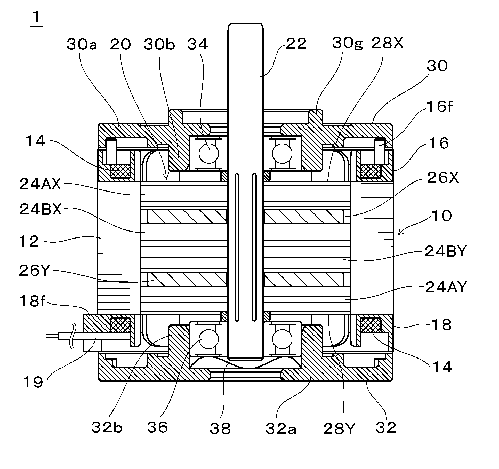
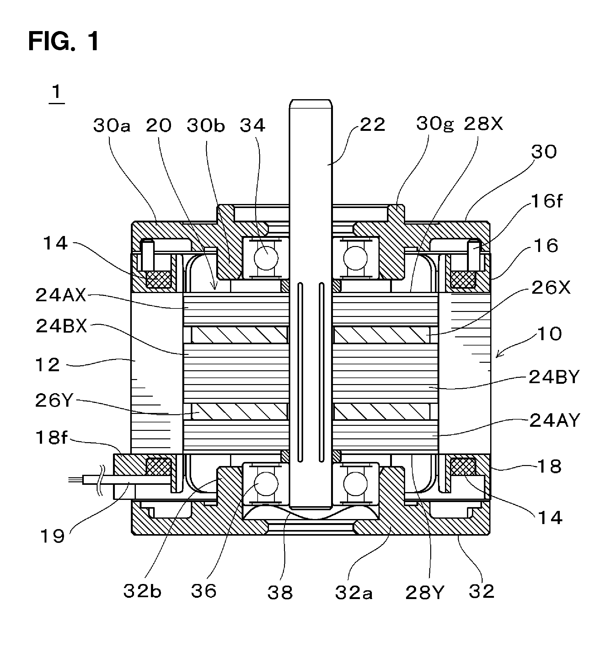
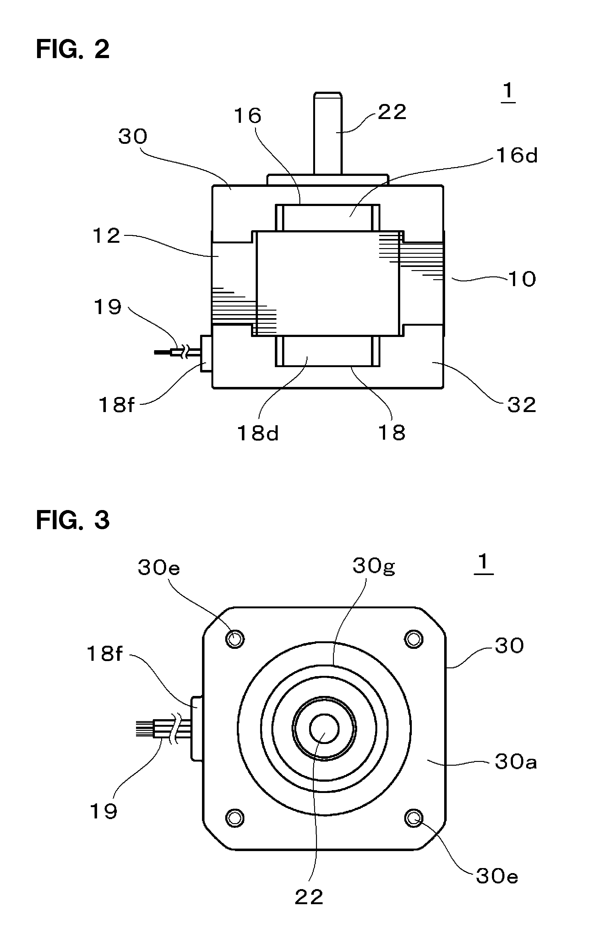
[0034]FIGS. 1 to 3 shows an overall configuration of a two-phase hybrid (HB) type stepping motor 1 according to a preferred embodiment of the present invention. FIG. 1 is a sectional front view of the stepping motor 1, FIG. 2 is a front view thereof, and FIG. 3 is a top view thereof. FIG. 4 shows a stator 10 including a two-phase eight-main-pole structure which does not generate an unbalanced electromagnetic force and which is superior in high-speed performance. FIG. 5 shows a stator core 12.

[0035]The stator 10 preferably includes a stator core 12 including a ring-shaped core-back portion 12a having a square or substantially square contour and eight main poles 12b protruding radially inward from the core-back portion 12a and arranged at a regular interval along the circumferential direction, a two-phase coil 14 (see FIGS. 1 and 4) wound around the respective main poles 12b, and upper and lower insulating members 16 and 18 interposed between the respective main poles 12b and the coil...

second preferred embodiment

[0062]Next, another preferred embodiment of the present invention will be described with reference to FIGS. 12 and 13. FIG. 12 is a sectional front view showing the overall configuration of a two-phase hybrid (HB) type stepping motor 1′ according to another preferred embodiment of the present invention. FIG. 13 is a partially enlarged view of the stepping motor shown in FIG. 12. In FIGS. 12 and 13, identical or equivalent elements or portions are designated by the same reference symbols as those used in FIGS. 1 to 11.

[0063]The stepping motor 1′ shown in FIG. 12 differs from the stepping motor of the foregoing preferred embodiment in terms of the frame portions 16b′ and 18b′ of the insulating members 16 and 18 of the stator 10. More specifically, each of the upper and lower insulating members 16 and 18 defining and serving as insulators preferably includes slot insulating portions 16a or 18a which cover the end surfaces and the opposite side surfaces of the main poles 12a of the stat...


PUM


Abstract

An inner-rotor-type motor, includes four outer surface portions flush or substantially flush with the motor outer surface of the core-back portion provided in the frame portion of each of the two insulating members of the insulator to secure electrical insulation between the stator core and the coil. The outer surface portions of the frame portion of each of the insulating members are inserted between the leg portions of four corners of each of the cover members attached to the axial opposite sides of the stator core. In this state, the cover members are attached to the stator core. The inner-rotor-type motor makes it possible to easily and cost-effectively manufacture a cover member without impairing the dust-proofness of the interior of the motor and greatly improves ease of assembly.

Description

BACKGROUND OF THE INVENTION[0001]1. Field of the Invention[0002]The present invention relates to an inner-rotor-type motor, such as, for example, a stepping motor or the like, which includes a stator provided by winding a coil around a plurality of main poles as winding poles and a rotor arranged inside the stator.[0003]2. Description of the Related Art[0004]Conventionally, a stepping motor is used in a drive portion in a wide variety of fields including an information device field such as a printer, a facsimile machine, a copier or the like and an industrial device field such as a factory automation device or the like. In case where the stepping motor of this kind is, e.g., a hybrid type that makes use of a magnetic body and a permanent magnet as a rotor, there have been widely used inner-rotor-type motors disclosed in Japanese Patent Application Publication Nos. 2002-051528 and 2001-112521.[0005]More specifically, a stator core is formed by installing a plurality of main poles in ...

Claims


Application Information

Patent Timeline
Patent Type & Authority Applications(United States)
IPC IPC(8): H02K5/15H02K5/16
CPCH02K5/161H02K5/15H02K3/522H02K5/10H02K37/14
Inventor KOJIMA, AKINORIKIKUCHI, NORIYOSHIKANEKO, EIJI
Owner NIDEC SERVO CORP
Features
  • R&D
  • Intellectual Property
  • Life Sciences
  • Materials
  • Tech Scout
  • Unparalleled Data Quality
  • Higher Quality Content
  • 60% Fewer Hallucinations
Learn More