Supercharge Your Innovation With Domain-Expert AI Agents!

Method for manufacturing a double pipe

a manufacturing method and technology for pipes, applied in the direction of machines/engines, other domestic objects, mechanical equipment, etc., can solve the problems of increased labor costs for managing (procuring) and handling liquid nitrogen, inability to reliably and readily form the prescribed air space between the inner and outer, and incur additional equipment and material costs. to achieve the effect of reducing equipment, material and labor costs

Active Publication Date: 2019-01-29
NAKAGAWA SANGYO
View PDF14 Cites 0 Cited by
  • Summary
  • Abstract
  • Description
  • Claims
  • Application Information

AI Technical Summary

Benefits of technology

The present patent attracts attention to a method for making a double pipe, such as a curved double pipe, in a simple and cost-effective way. The method involves inserting a curved inner pipe into a curved half pipe, which is then bent to form a circular shape around the half pipe, forming a coating of inner and outer pipes. This method avoids the need for costly equipment, materials, and labor, and ensures that the double pipe has a consistent annular gap along its length. The method can also be used to easily weld and suspend the inner pipe within the outer pipe, improving insulation. Overall, this method simplifies the manufacturing process for curved double pipes.

Problems solved by technology

However, if the curved exhaust pipe is formed simply by bending a straight double pipe, the curved portion becomes flattened, which means that a prescribed air space (clearance) can not be reliably and readily formed between the inner pipe and the outer pipe.
Because it is necessary to quickly freeze the water to form the ice, the above-described known manufacturing method incurs additional equipment and material costs due to the use of pressurized liquid nitrogen.
Moreover, it involves additional labor costs for the managing (procuring) and handling the liquid nitrogen.

Method used


Image

  • Method for manufacturing a double pipe
  • Method for manufacturing a double pipe
  • Method for manufacturing a double pipe

Examples


Embodiment Construction

[0026]The manufacturing method that will be described below is merely a representative, non-limiting example of the present teachings, and various design improvements or modifications, which can made by those skilled in the art without departing from the gist of the present invention, are also intended to be included in the scope of the present invention.

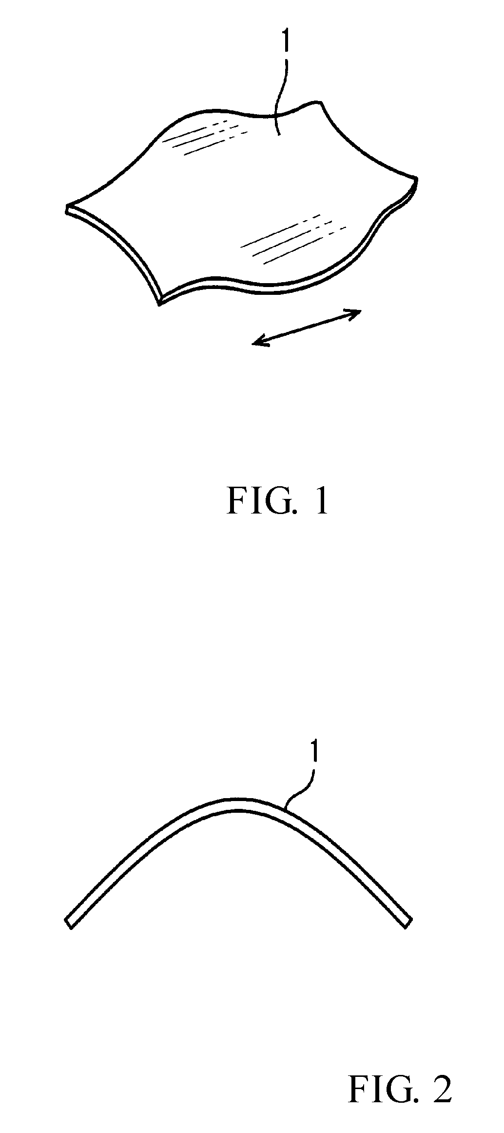
[0027]In a representative manufacturing method of the present teachings, a stainless-steel or titanium (or titanium alloy) metal plate 1 is formed into a predetermined shape (blank) by blanking, e.g., cutting or punching, as shown in FIG. 1. The optimal blank shape may be determined empirically such that an outer pipe having a predetermined curved shape can be obtained after the subsequent metal working (shaping) steps. The shape of the blank thus need only be determined once prior to mass production.

[0028]Next, as shown in FIG. 2, the plate (blank) 1 optionally may be bent or deformed (plastically deformed), e.g., by stamping, into...


PUM

PropertyMeasurementUnit
shapeaaaaaaaaaa
curved shapeaaaaaaaaaa
diameteraaaaaaaaaa

Abstract

A method for manufacturing a double pipe includes: drawing a plate (1), which has a predetermined shape corresponding to the desired final shape of a curved outer pipe (4), into a curved, substantially U-shape in cross-section to produce a half pipe (2). Then, an inner pipe (3), which has a curved shape similar to the desired final curved shape of the outer pipe, is inserted into and positioned within the interior space of the half pipe. Subsequently, the inner pipe is welded to the half pipe at one longitudinal end thereof. Thereafter, longitudinally-extending edges of the half pipe are curled towards each other until they abut and a substantially circular cross-section is formed that surrounds the exterior of the inner pipe. The abutting longitudinally-extending edges (22) of the half pipe are then welded together to produce the curved outer pipe (4).

Description

CROSS-REFERENCE[0001]This application claims priority to Japanese patent application no. 2015-237034 filed on Dec. 4, 2015, the contents of which are incorporated by reference as if fully set forth herein.BACKGROUND OF THE INVENTION[0002]Field of the Invention[0003]The present invention generally relates to a method for manufacturing a double pipe, such as a method for manufacturing a curved double pipe.[0004]Description of the Related Art[0005]Catalytic converters are utilized, e.g., in vehicles, to convert toxic pollutants, such as carbon monoxide, unburned hydrocarbons and nitrogen oxides, into less toxic or non-toxic substances, such as carbon dioxide, water and nitrogen gas. To perform this purification, catalytic converters utilize a “redox” (i.e. reduction and oxidation) catalyst (purification catalyst) that typically functions most optimally or efficiently at a predetermined temperature or higher. Therefore, to avoid a decrease in the temperature of an exhaust gas flowing fr...

Claims


Application Information

Patent Timeline
Patent Type & Authority Patents(United States)
IPC IPC(8): F01N13/14B21D51/16B21D5/10F01N13/18
CPCF01N13/143B21D5/10B21D51/16F01N13/1872F01N2530/02F01N2450/22F01N2470/24
Inventor NAKAGAWA, NORIAKI
Owner NAKAGAWA SANGYO
Features
  • R&D
  • Intellectual Property
  • Life Sciences
  • Materials
  • Tech Scout
  • Unparalleled Data Quality
  • Higher Quality Content
  • 60% Fewer Hallucinations
Learn More