Vehicle air conditioner

a technology for air conditioners and vehicles, applied in vehicle components, vehicle heating/cooling devices, transportation and packaging, etc., can solve the problem of early change in temperature of the vehicle interior, and achieve the effect of prolonging the period during which the idling stop is implemented

Active Publication Date: 2015-04-30
DENSO CORP
View PDF0 Cites 8 Cited by
  • Summary
  • Abstract
  • Description
  • Claims
  • Application Information

AI Technical Summary

Benefits of technology

[0020]On the contrary, according to the above-described aspect of the present disclosure, when it is determined that it is immediately before the idling stop, as described above, the conditioned air can be blown out of the outlet port corresponding to the seat in which the occupant is not seated. Hence, the temperature change of air blown from the outlet port into the vehicle interior can be restricted. As a result, the period during which the idling stop is implemented can be prolonged.

Problems solved by technology

That is, when the travel engine stops due to the idling stop during the implementation of the occupant intensive air-conditioning mode control, the temperature of the vehicle interior may change early.

Method used


Image

  • Vehicle air conditioner
  • Vehicle air conditioner
  • Vehicle air conditioner

Examples


first embodiment

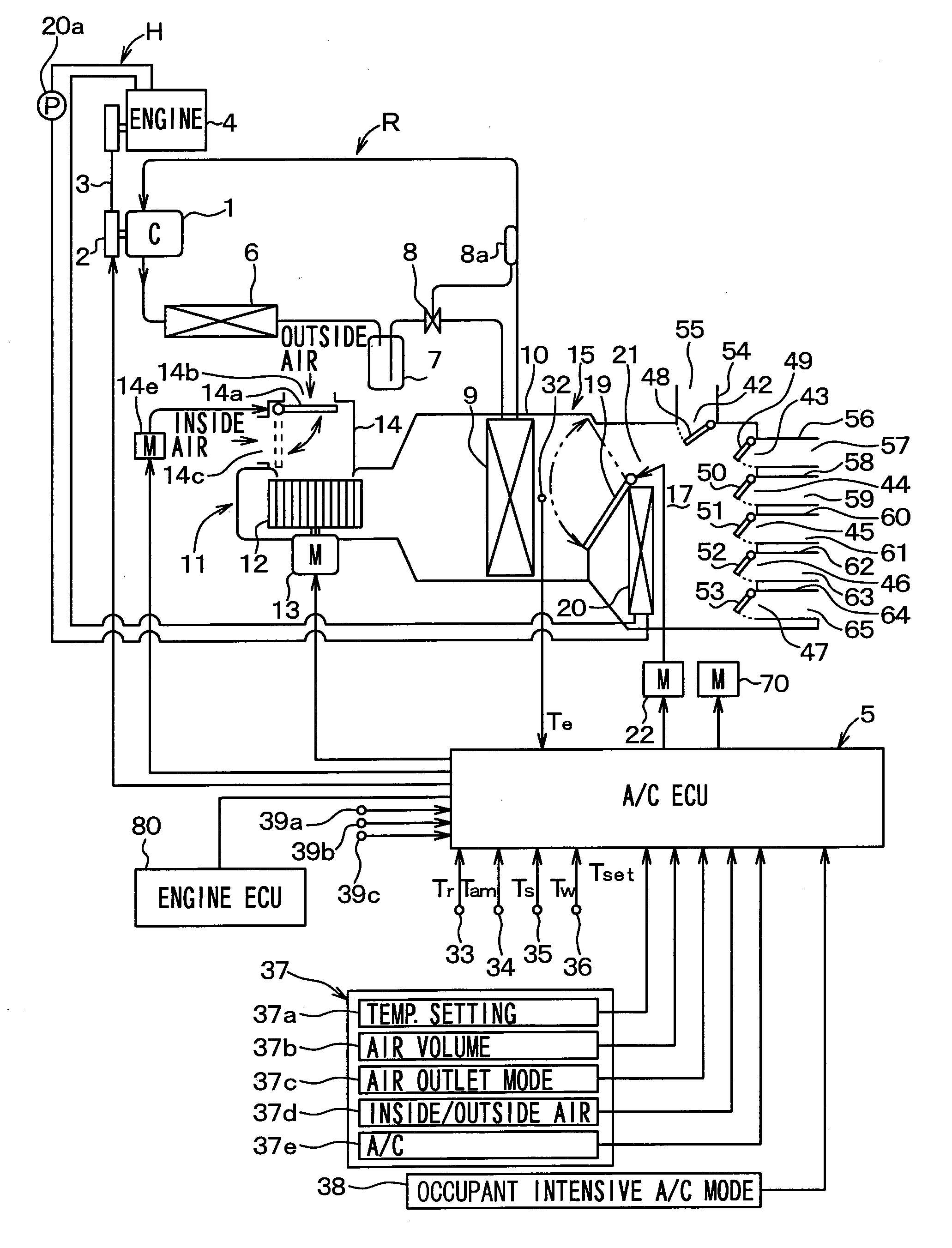
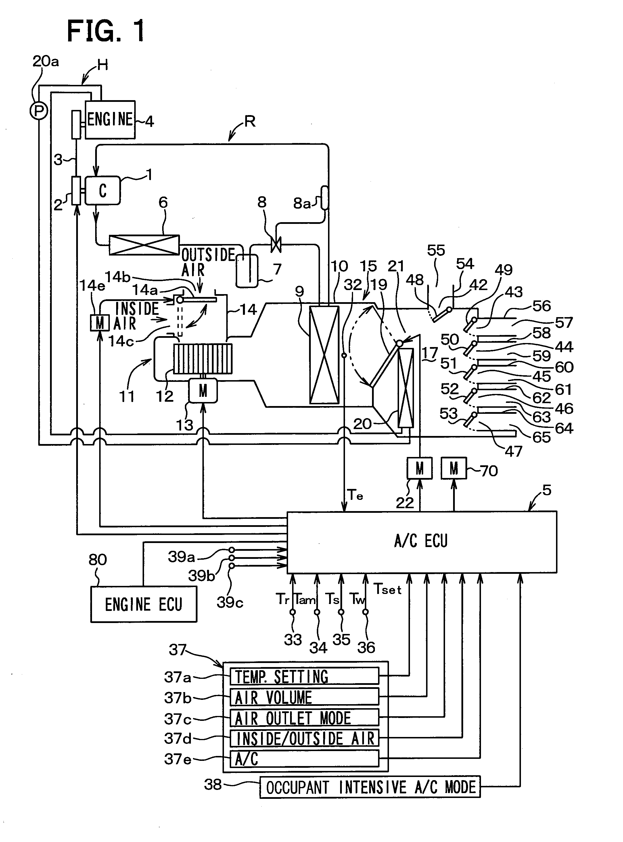
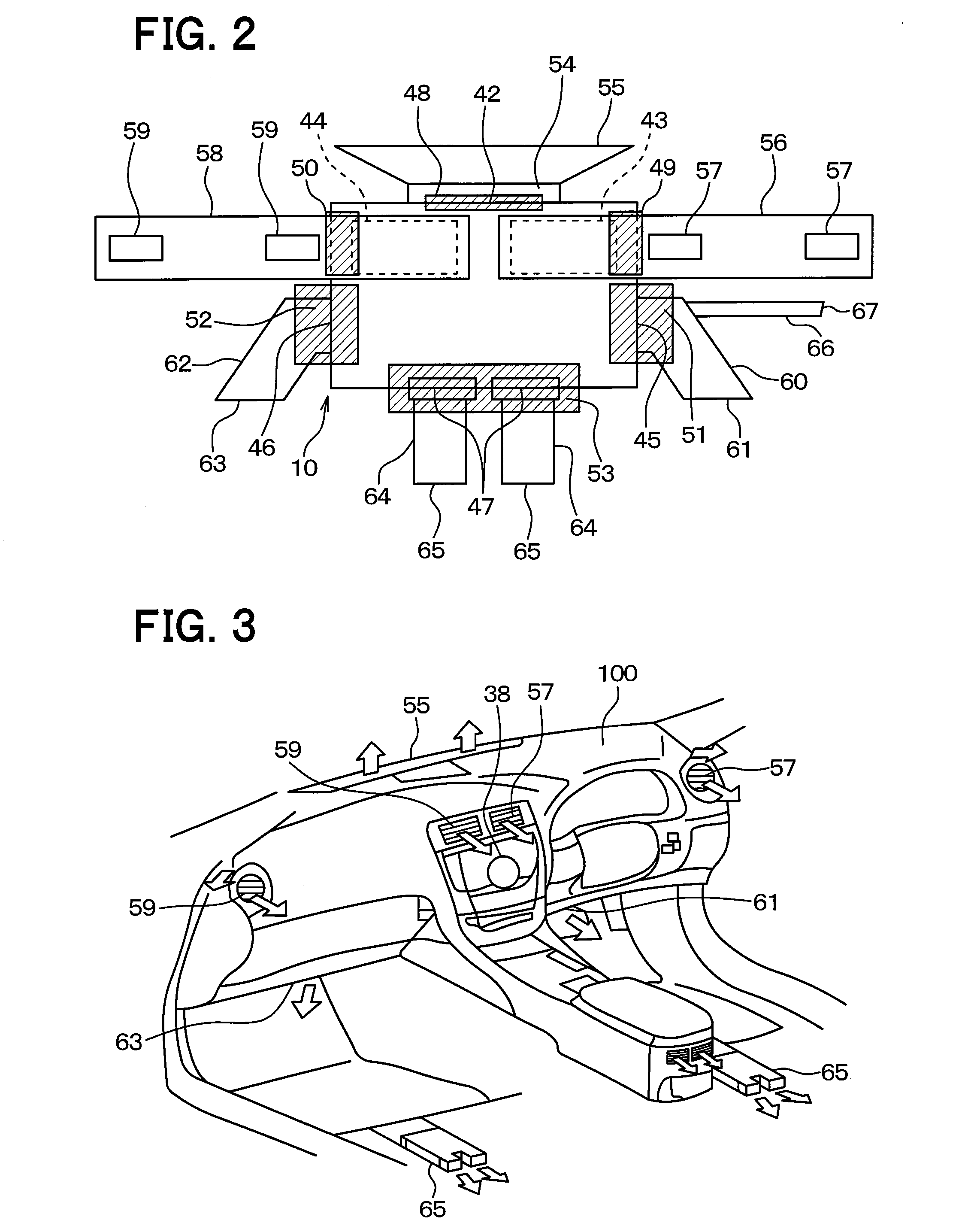
[0041]FIGS. 1 to 3 illustrate a vehicle air conditioner according to the present embodiment. FIG. 1 is a diagram illustrating an overall configuration of a vehicle air conditioner according to the present embodiment. FIG. 2 is a top view of the vehicle air conditioner according to the present embodiment, and FIG. 3 is a diagram illustrating a vehicle interior outlet port of the vehicle air conditioner according to the present embodiment.

[0042]A vapor compression refrigeration cycle device R of a vehicle air conditioner in FIG. 1 is equipped with a compressor 1 that sucks, compresses, and discharges a refrigerant by a kinetic energy output from a travel engine 4. Specifically, the compressor 1 has an electromagnetic clutch 2, and the kinetic energy (motive power) output from the travel engine 4 is transmitted to the compressor 1 through the electromagnetic clutch 2 and a belt 3. The energization to the electromagnetic clutch 2 is intermittently implemented by an electronic control un...

second embodiment

[0121]In the above-mentioned first embodiment, the example in which when it is determined that the travel engine 4 is operating as no in Step S26 of FIG. 5, the front seat air conditioning mode is implemented in association with this determination has been described. Alternatively, in the present embodiment, a description will be given of an example in which when it is determined that the travel engine 4 is operating as no, and the air conditioning load within the vehicle interior is equal to or higher than a threshold, the front seat air conditioning mode is implemented.

[0122]FIG. 8 is a flowchart illustrating a sub control process according to the present embodiment. In the present embodiment, a flowchart in FIG. 8 will be applied instead of the flowchart in FIG. 5. In FIG. 8, Step S29 is added between Step S26 and Step S28 in FIG. 5. Under the circumstances, hereinafter, in a description of the sub control process according to the present embodiment, a description of common steps...

third embodiment

[0137]In the above first and second embodiments, a description has been given of the example in which whether the continuous operation time of the travel engine 4 is lower than the predetermined time t, or not, is determined in Step S20a of the sub control process in FIG. 5, to thereby determine whether it is immediately before the idling stop, or not. Alternatively, the determination may be conducted as follows.

[0138]FIG. 11 is a flowchart illustrating a sub control process according to the present embodiment. A flowchart in FIG. 11 will be applied instead of the flowchart in FIG. 5. Steps other than Step S20b in FIG. 11 are identical with those in FIG. 5. Hereinafter, Step S20b in the present embodiment will be described.

[0139]In Step S20b of the present embodiment, the operation rate of the travel engine 4 is calculated on the basis of a signal output from the engine ECU 80. The operation rate of the travel engine 4 is a ratio of an operation time of the travel engine 4 to a pred...


PUM


Abstract

When an air conditioning ECU determines that it is immediately before idling stop, the air conditioning ECU implements a front seat air conditioning mode even if the air conditioning ECU determines that an occupant intensive air-conditioning mode can be implemented. Accordingly, the air conditioning ECU controls opening and closing mechanisms so as to blow a conditioned air from driver's seat side outlet ports, and also blow the conditioned air from a passenger's seat side foot outlet port. Hence, in cooling operation, since a temperature increase of air drawn into an inside air inlet port is limited when the idling stop is carried out, temperature increase of air blown into the vehicle interior from the outlet port can be restricted. In other words, a temperature change in the vehicle interior can be limited when a travel engine stops due to the idling stop.

Description

CROSS REFERENCE TO RELATED APPLICATION[0001]This application is based on and incorporates herein by reference Japanese Patent Application No. 2012-090196 filed on Apr. 11, 2012.TECHNICAL FIELD[0002]The present disclosure relates to a vehicle air conditioner.BACKGROUND ART[0003]Up to now, there is a disclosure of an occupant intensive air-conditioning mode control that limits an air blowing rate blown out of a conditioned air outlet port facing the seat in which no passenger is seated if it is detected that a passenger is not seated in a seat (for example, a passenger seat) other than a driver's seat in a vehicle air conditioner (refer to Patent Document 1).[0004]Also, in Non-Patent Document 1, an idling stop system is disclosed, which automatically stops an engine when a driver stops a vehicle to wait for a traffic light.PRIOR ART DOCUMENTPatent Document[0005]Patent Document 1: JP 2005-145327 A[0006]Non-Patent Document 1: Mazda, Idling Stop, “Searched on Mar. 13, 2011”, Internet <...

Claims


Application Information

Patent Timeline
Patent Type & Authority Applications(United States)
IPC IPC(8): B60H1/00B60H1/32
CPCB60H1/3204B60H1/00778B60H1/00742B60H1/00821
Inventor OTA, KOJISAGOU, YASUHIRO
Owner DENSO CORP
Why Eureka
Try Eureka