Exhaust muffler for vehicle

a technology for exhaust mufflers and vehicles, which is applied in the direction of engines, mechanical equipment, machines/engines, etc., can solve the problems of high cost and difficult manufacture of spark arresters, and achieve the effect of avoiding an excessive increase in the diameter of the exit communication pipes

Active Publication Date: 2015-04-30
KAWASAKI MOTORS LTD
View PDF10 Cites 4 Cited by
  • Summary
  • Abstract
  • Description
  • Claims
  • Application Information

AI Technical Summary

Benefits of technology

[0009]With the structure described above, the spark arrester is not arranged in the expansion chamber but in the exit communication pipe. Further, the exhaust flow path narrowing portion is provided at the entrance portion of the exit communication pipe. Thus, the back pressure acting on the spark arrester can be reduced, whereby deformation due to back pressure of the spark arrester can be suppressed. As a result, the reinforce member can be dispensed with, and designing of the spark arrester can be streamlined.
[0012]With the structure (1), since the spark arrester is structured by a mesh-like member, the productivity of the spark arrester can be improved and costs can be reduced.
[0013]Furthermore, since no reinforce member covers the surface of the spark arrester, the filter portion of the spark arrester can be secured for the entire surface. As a result, the spark arrester can be structured in a compact manner.
[0015]With the structure (2), the exhaust flow path narrowing portion can be easily formed. Further, as compared with the case where a tapered narrowing portion is formed, the exhaust flow path can be sharply narrowed, and the back pressure in the exit communication pipe can be more effectively reduced. Thus, deformation caused by the back pressure of the spark arrester can be further suppressed.
[0017]With the structure (3), while realizing a reduction in the back pressure, it becomes possible to secure the exhaust flow path of proper size, and to avoid a reduction in the engine performance attributed to an excessive increase in the back pressure.
[0019]With the structure (4), it becomes possible to avoid an excessive increase in the diameter of the exit communication pipe, whereby the muffler body can be structured in a compact manner.

Problems solved by technology

Therefore, since the structure is complicated, manufacturing of the spark arrester is not easy and involves high costs.

Method used


Image

  • Exhaust muffler for vehicle
  • Exhaust muffler for vehicle
  • Exhaust muffler for vehicle

Examples


embodiment

[Overall Structure]

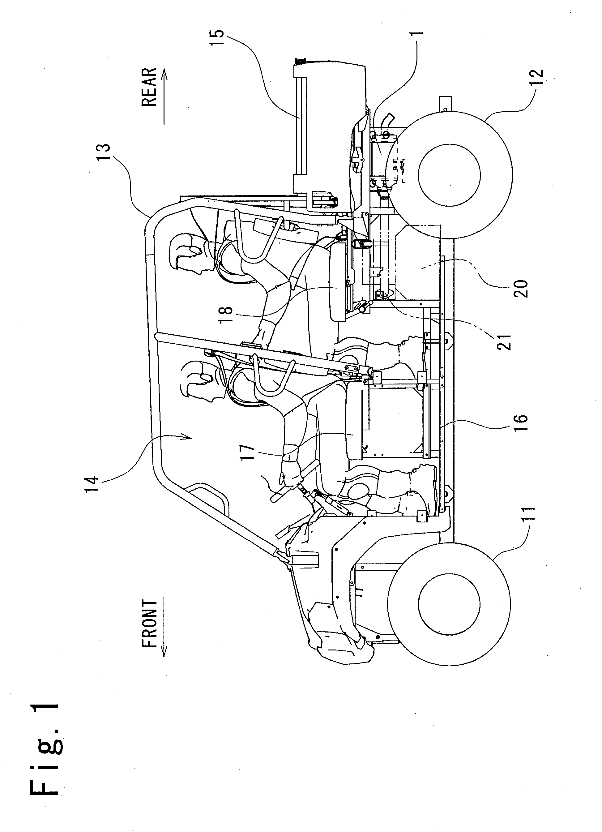
[0030]In the following, with reference to the accompanying drawings, a description will be given of one embodiment of the present invention. Note that, for the sake of convenience in describing, the following description is based on the premise that the front-rear direction of a vehicle is applied to the front-rear direction of the exhaust muffler and other components, and that the right-left direction in connection with the vehicle-width direction (the right and left sides as seen from the rear of the vehicle) as seen from the passengers on the vehicle is applied to the right-left direction of the exhaust muffler and other components.

[0031]FIG. 1 is a left side view of a utility vehicle according to the present embodiment, with shell constituent members such as doors being removed. As shown in FIG. 1, the utility vehicle includes: a right and left pair of front wheels 11 on the front side and a right and left pair of rear wheels 12 on the rear side; a passenger s...


PUM


Abstract

An exhaust muffler for a vehicle includes a muffler body coupled to an exhaust pipe and a tailpipe coupled to the muffler body. The muffler body has a plurality of expansion chambers, an exit communication pipe that discharges exhaust to the tailpipe from one of the plurality of expansion chambers positioned in a most downstream part of an exhaust flow path, and a spark arrester arranged in the exit communication pipe. An exhaust flow path narrowing portion is provided at an entrance portion of the exit communication pipe.

Description

BACKGROUND OF THE INVENTION[0001]1. Field of the Invention[0002]The present invention relates to an exhaust muffler for a vehicle. In particular, the present invention relates to a spark arrester provided in an exhaust muffler for a vehicle.[0003]2. Description of the Related Art[0004]Conventionally, an exhaust muffler for a vehicle including a spark arrester is known. In general, the spark arrester is formed by a mesh-like member made of metal.[0005]Meanwhile, since the spark arrester is arranged in an exhaust flow path in the exhaust muffler and exposed to exhaust gas, it is required to be so durable that it does not deform under conditions of high temperatures and high back pressure with an exhaust pulse. Accordingly, the spark arrester is provided with a frame member for reinforcing a mesh-like member made of a metal mesh. Thus, the spark arrester is prevented from deforming under the foregoing conditions. There is Prior Technique Document JP 8-61046 A.[0006]That is, the spark a...

Claims


Application Information

Patent Timeline
Patent Type & Authority Applications(United States)
IPC IPC(8): F01N13/08
CPCF01N13/082F01N1/084F01N1/089F01N1/10F01N3/2885F01N2230/06F01N2340/02F01N2450/22F01N2470/20F01N13/0097Y02A50/20
Inventor YOSHIDA, ATSUYA
Owner KAWASAKI MOTORS LTD
Why Eureka
Try Eureka