
Connecting device for electrically connecting two circuit boards

a technology of connecting device and circuit board, which is applied in the direction of two-part coupling device, securing/insulating coupling contact member, electrical apparatus, etc., can solve the problems of electrical transmission properties impairment of the connecting device, and achieve low intermodulation level and good electric transmission properties

Active Publication Date: 2015-04-30
TELEGARTNER KARL GARTNER
View PDF0 Cites 19 Cited by
  • Summary
  • Abstract
  • Description
  • Claims
  • Application Information

AI Technical Summary

Benefits of technology

The invention is a connecting device used to connect circuit boards. The device consists of a coupling member that is supported by an elastically deformable holding ring against the outer conductor of a coaxial connector. The holding ring compensates for positional inaccuracies and relative movements of the circuit boards, but also counteracts vibrations of the coupling member. The design of the coupling member and holding ring ensures that the electric transmission properties of the connecting device are not significantly affected by the positional inaccuracies or movements. The holding ring is made of a dielectric material and has an inner surface that is in line contact with the outer conductor of the coaxial connector, preventing a sudden change in geometry and thus intermodulation production. The technical effects of this invention are improved reliability and stability of the connecting device, compensating for positional inaccuracies and relative movements of the circuit boards.

Problems solved by technology

However, the elastically deformable holding ring counteracts micromovements of the coupling member which could lead to abrasion and therefore impairment of the electric transmission properties of the connecting device.

Method used


Image

  • Connecting device for electrically connecting two circuit boards
  • Connecting device for electrically connecting two circuit boards
  • Connecting device for electrically connecting two circuit boards

Examples


Embodiment Construction

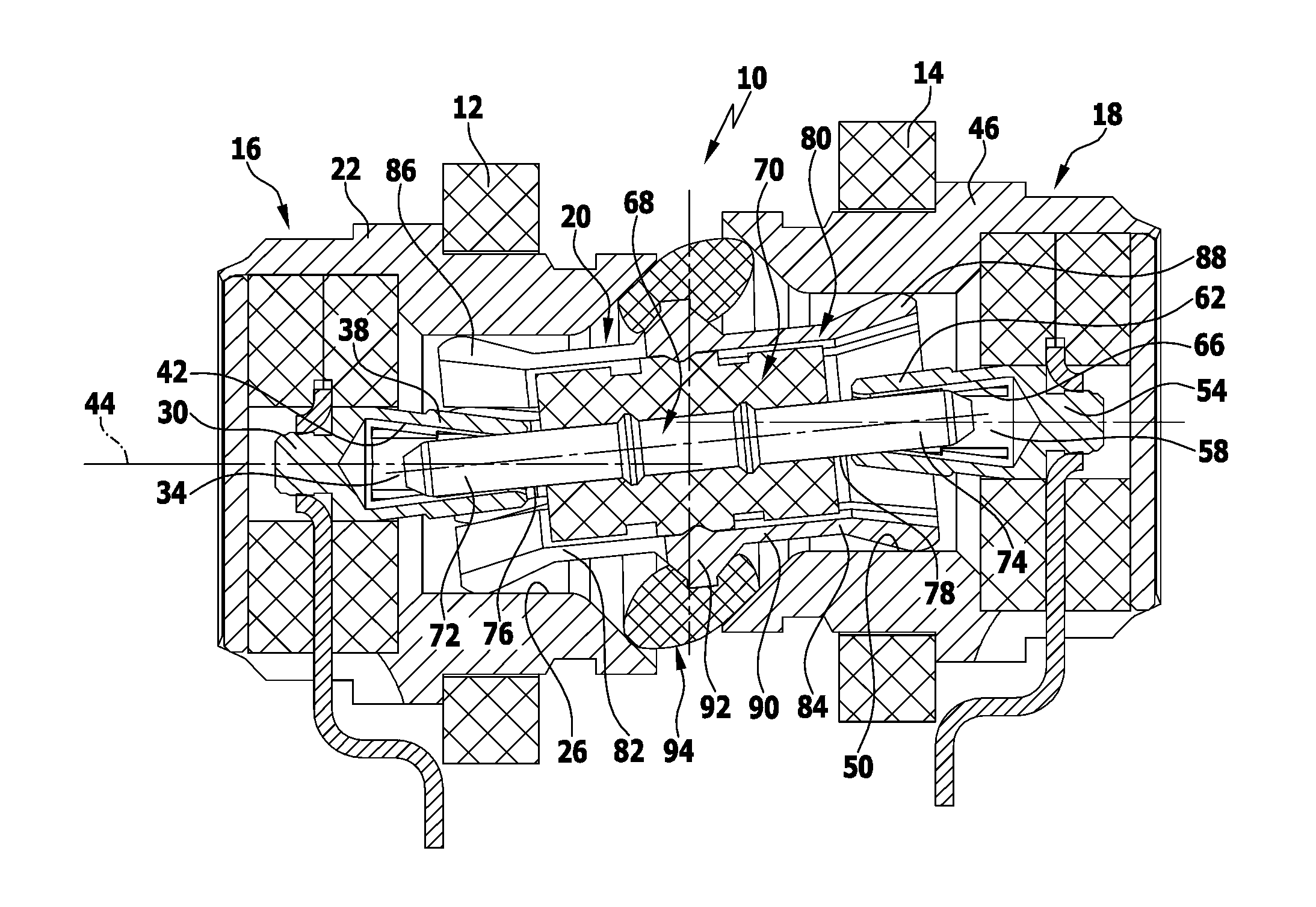
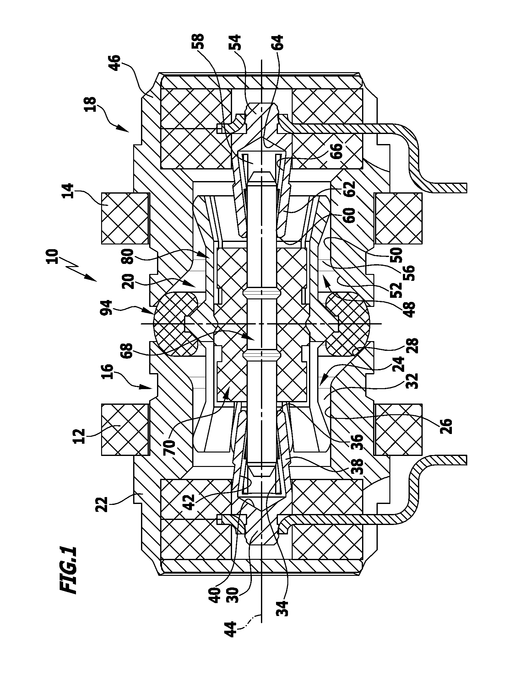
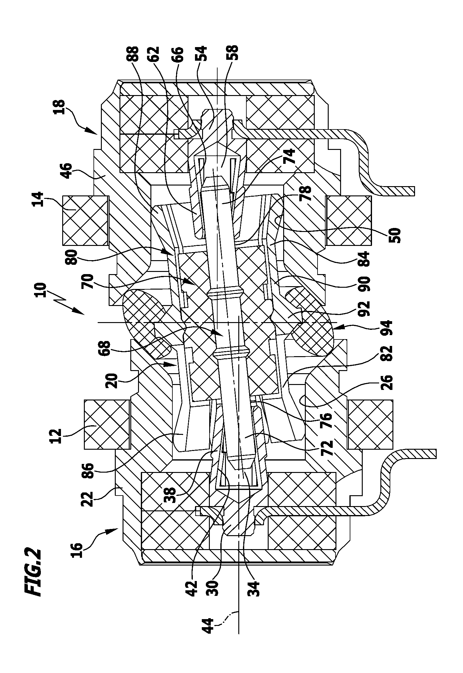
[0035]Schematically represented in FIGS. 1 and 2 is a first advantageous embodiment of a connecting device constructed in accordance with the invention, generally designated by the reference numeral 10. The connecting device 10 makes it possible for a first circuit board 12 to be electrically conductively connected to a second circuit board 14. To this end, the connecting device 10 has a first coaxial connector 16 and a second coaxial connector 18 and a coupling member 20 movably arranged between the two coaxial connectors 16, 18.

[0036]The first coaxial connector 16 is held on the first circuit board 12 and has a first outer conductor 22 which is configured in the manner of a socket and has a first recess 24 with a cylindrical middle section 26 and a conically diverging end section 28 which adjoins the cylindrical middle section 26 of the first recess 24 in a direction towards the second circuit board 14.

[0037]Arranged in the first recess 24 is a first inner conductor 30 of the firs...


PUM


Abstract

A connecting device for electrically connecting two circuit boards is provided. The connecting device has a first and a second coaxial connector and a coupling member. The two coaxial connectors and the coupling member each have an outer conductor and an inner conductor. The outer conductors of the coaxial connectors are electrically interconnected via the outer conductor of the coupling member and the inner conductors of the coaxial connectors are electrically interconnected via the inner conductor of the coupling member. The coupling member is arranged between the two coaxial connectors so as to be tiltable from an axially aligned orientation and displaceable in an axial direction. The coupling member is held on an elastically deformable dielectric holding ring which surrounds the coupling member in a circumferential direction and is in contact against at least one coaxial connector.

Description

[0001]This application claims the benefit of German patent application number 10 2013 111 905.0 filed on Oct. 29, 2013, which is incorporated herein by reference in its entirety and for all purposes.BACKGROUND OF THE INVENTION[0002]The invention relates to a connecting device for electrically connecting two circuit boards, the connecting device comprising a first and a second coaxial connector and a coupling member, wherein the two coaxial connectors and the coupling member each have an outer conductor and an inner conductor and the outer conductors of the coaxial connectors are electrically interconnected via the outer conductor of the coupling member and the inner conductors of the coaxial connectors are electrically interconnected via the inner conductor of the coupling member and wherein the coupling member is arranged between the two coaxial connectors so as to be tiltable from an axially aligned orientation and displaceable in an axial direction.[0003]Electrical installations ...

Claims


Application Information

Patent Timeline
Patent Type & Authority Applications(United States)
IPC IPC(8): H01R24/50H01R12/71
CPCH01R12/716H01R24/50H01R12/91H01R13/5219H01R24/542
Inventor BAECHLE, ERIKVOGL, REINHARDKRUEGEL, GERD
Owner TELEGARTNER KARL GARTNER
Learn More