Ultrasonic diagnosis apparatus

Active Publication Date: 2015-04-30
GE MEDICAL SYST GLOBAL TECH CO LLC
View PDF13 Cites 6 Cited by
  • Summary
  • Abstract
  • Description
  • Claims
  • Application Information

AI Technical Summary

Benefits of technology

[0011]According to the above-mentioned first aspect, notification is performed to let the transmission timing of the push pulses be recognized on the basis of the detection by the respiration detection part. Thus when the same location of the tissue is measured a number of times for elasticity, the push pulses may be transmitted for elasticity measurement at the timing at which the effects of body movement by respiration are minimal. This makes it possible suitably to measure the same location of the tissue.
[0012]According to the above-mentioned second aspect, the push pulses are transmitted at the timing at which the body movement induced by respiration is minimal on the basis of the detection by the respiration detection part. Thus when the same location of the tissue is measured a number of times for elasticity, the push pu

Problems solved by technology

In such cases, if the biological tissue is moved by respiration, the location being measured is shifted, which renders the measuring of the same location difficult.
However, it is sometimes difficult for the test object to keep stopping his or her respiration.
Furthermore, the biological tissue may remain still but the position and angle of the ultrasonic probe may change during measurement

Method used


Image

  • Ultrasonic diagnosis apparatus
  • Ultrasonic diagnosis apparatus
  • Ultrasonic diagnosis apparatus

Examples


first embodiment

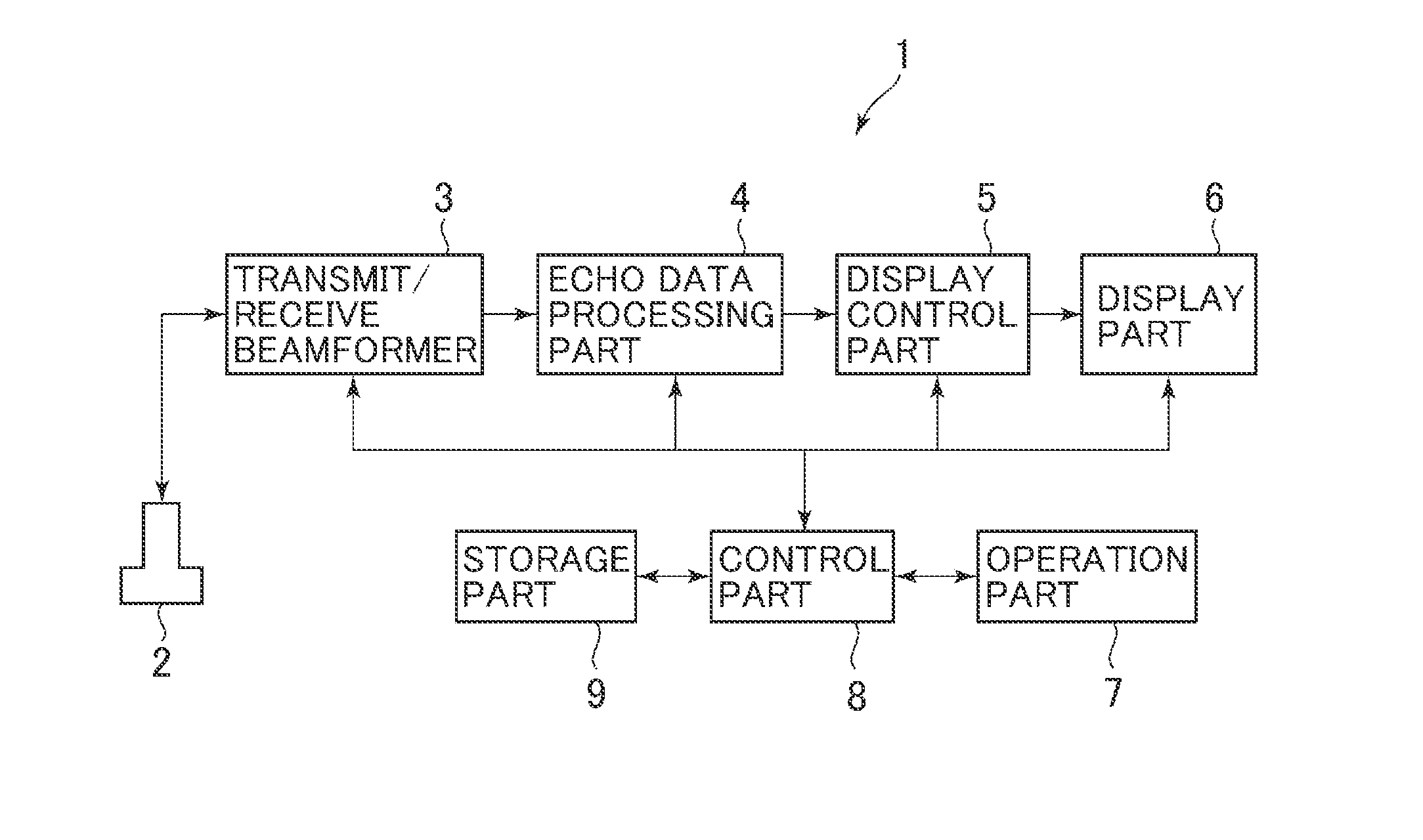
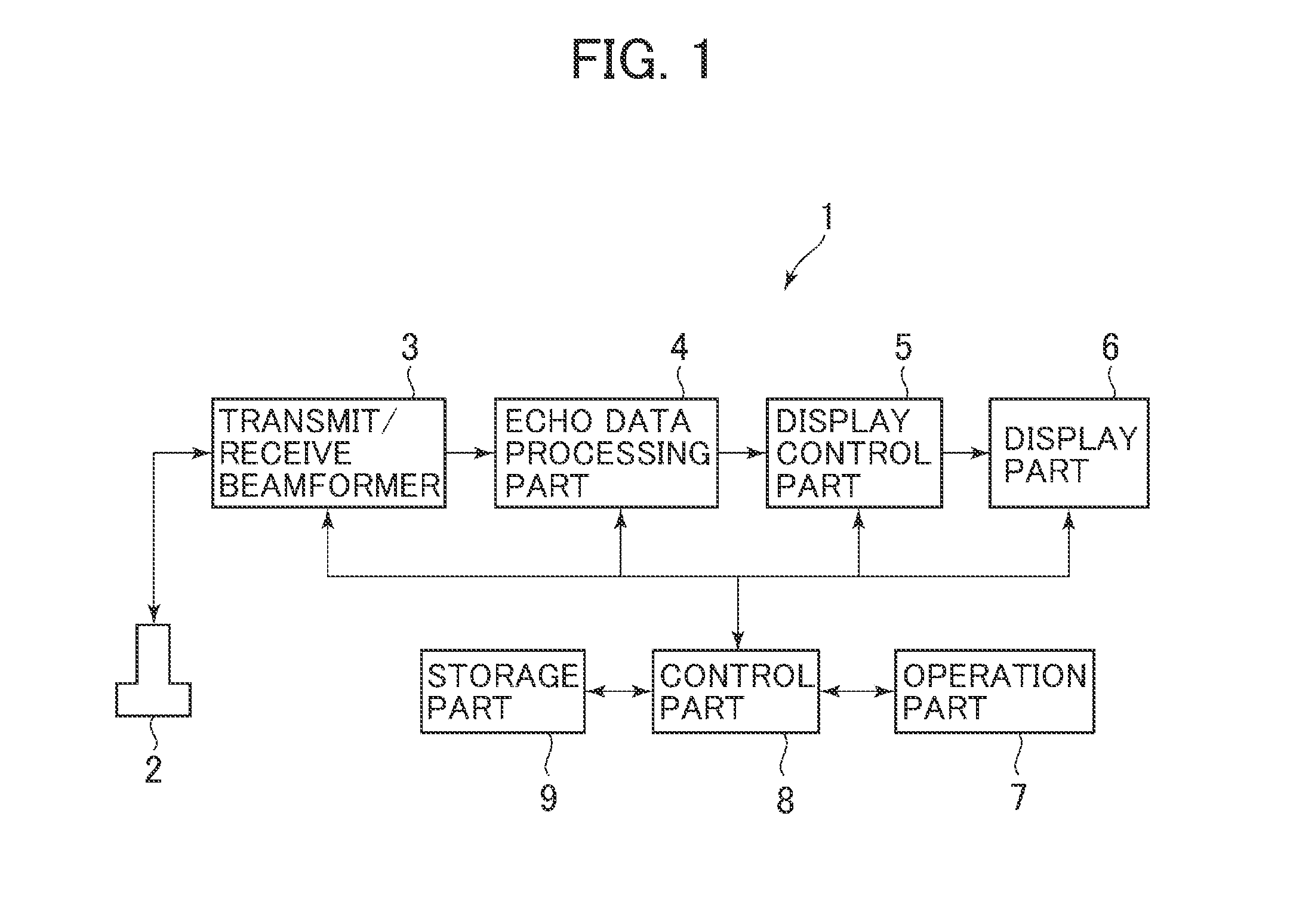
[0058]The first embodiment is explained first. An ultrasonic diagnosis apparatus 1 shown in FIG. 1 includes an ultrasonic probe 2, a transmit / receive beamformer 3, an echo data processing part 4, a display control part 5, a display part 6, an operation part 7, a control part 8, and a storage part 9.

[0059]The ultrasonic probe 2 transmits ultrasonic weaves to a biological tissue of a test object. This ultrasonic probe 2 transmits ultrasonic pulses (push pulses) to the biological tissue to generate shear waves therein. The ultrasonic probe 2 also transmits measuring ultrasonic pulses for measuring a propagation velocity of the shear waves and receives an echo signal of the transmitted measuring ultrasonic pulses. The ultrasonic probe 2 further transmits imaging ultrasonic waves for generating an ultrasonic image such as a B-mode image and receives an echo signal of the transmitted imaging ultrasonic waves. The ultrasonic probe 2 is an example of the ultrasonic probe.

[0060]On the basis ...

second embodiment

[0112]The second embodiment is explained below. The ensuing explanation will focus on the differences between the first and the second embodiments. Those components of the second embodiment which are substantially the same in structural terms as those discussed in connection with the first embodiment will be designated by the same reference numerals, and they will not be explained further in detail.

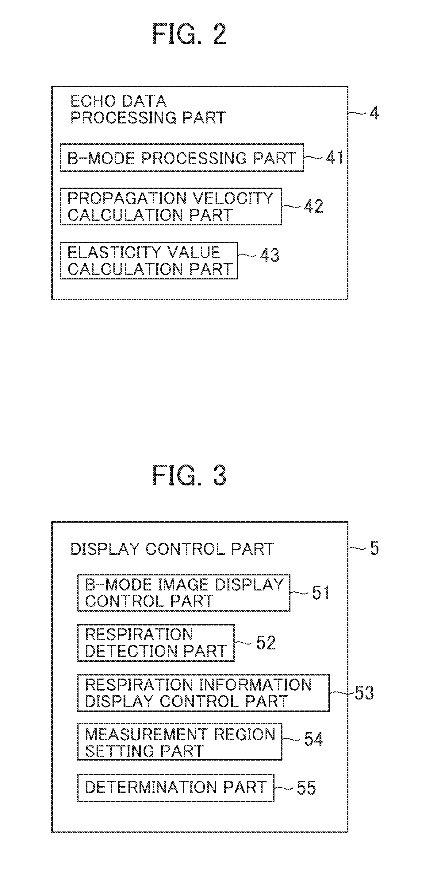
[0113]The ultrasonic diagnosis apparatus of the second embodiment has the same configuration as that shown in FIG. 1. The echo data processing part 4 of the second embodiment has the same configuration as that shown in FIG. 2. In the second embodiment, the display control part 5 has an image display control part 56, a movement detection part 57, a movement information display control part 58, and a region-of-interest setting part 59 as shown in FIG. 18.

[0114]The image display control part 56 generates B-mode image data by scan-converting the B-mode data using a scan converter, and causes ...

third embodiment

[0159]The third embodiment is explained below. The ensuing explanation will focus on the differences between the third embodiment on the one hand and the first and the second embodiments on the other hand. Those components of the third embodiment which are substantially the same in structural terms as those discussed in connection with the first and the second embodiments will be designated by the same reference numerals, and they will not be explained further in detail.

[0160]The ultrasonic diagnosis apparatus of the third embodiment has the same configuration as that shown in FIG. 1. The echo data processing part 4 of the third embodiment has the same configuration as that shown in FIG. 2. The display control part 5 of the third embodiment has the same configuration as that shown in FIG. 23.

[0161]The workings of the third embodiment are explained below. As with the second embodiment, the elasticity image EI is displayed within the region of interest R. The operations involved will ...


PUM


Abstract

An ultrasonic diagnosis apparatus is provided. The ultrasonic diagnosis apparatus includes an ultrasonic probe configured to transmit ultrasonic push pulses to a biological tissue of a test object and further configured to transmit measuring ultrasonic pulses to the biological tissue subjected to the transmitted push pulses in order to measure an elasticity of the biological tissue, a respiration detection part configured to detect respiration of the test object, and a notification part which, based on the detection by the respiration detection part, is configured to give notification allowing a transmission timing of the push pulses to be recognized.

Description

CROSS REFERENCE TO RELATED APPLICATIONS[0001]This application claims the benefit of Japanese Patent Application No. 2013-221254 filed Oct. 24, 2013, which is hereby incorporated by reference in its entirety.BACKGROUND[0002]The present invention relates to an ultrasonic diagnosis apparatus for measuring the elasticity of biological tissues by sending ultrasonic push pulses thereto.[0003]There are known elasticity measuring techniques for measuring the elasticity of biological tissues by transmitting ultrasonic pulses of high sound pressure (push pulses) thereto from an ultrasonic probe (e.g., see Japanese Unexamined Patent Publication No. 2012-100997). A typical measuring technique that utilizes the push pulses involves using an echo signal of measuring ultrasonic pulses to detect a propagation velocity of shear waves generated by vibration of the biological tissue subject to the push pulses, the detected propagation velocity being used as the basis for calculating an elasticity coef...

Claims


Application Information

Patent Timeline
IPC IPC(8): A61B8/08
CPCA61B8/5276A61B8/485A61B8/5207A61B8/543A61B8/5223G01S7/52074A61B8/06A61B8/085A61B8/14
Inventor KAWAE, SOTAROTANIGAWA, SHUNICHIROSAMSET, EIGILMACDONALD, MICHAEL CHARLES
Owner GE MEDICAL SYST GLOBAL TECH CO LLC
Why Eureka
Try Eureka