
Control device, robot, robot system, and control method

Inactive Publication Date: 2015-04-30
SEIKO EPSON CORP
View PDF13 Cites 14 Cited by
  • Summary
  • Abstract
  • Description
  • Claims
  • Application Information

AI Technical Summary

Benefits of technology

The patent text describes a control system for a robot that uses multiple images to control its operation. The system can receive two different types of operation information and use them to control the robot's movement. This helps ensure that the robot can reliably move the workpiece to its target position. Overall, the invention provides a control device, a robot, a robot system, and a control method that improve the efficiency and accuracy of workpiece movement.

Problems solved by technology

However, JP-A-2013-154446 does not disclose a method of moving the workpieces to respective assembly positions.

Method used


Image

  • Control device, robot, robot system, and control method
  • Control device, robot, robot system, and control method
  • Control device, robot, robot system, and control method

Examples


Embodiment Construction

[0099]Hereinafter, a preferred embodiment of the invention will be described in detail. The aspects of the invention are not unduly limited to the embodiment to be described below, and the entirety of configurations to be described in the embodiment is not always required as solution means of the invention.

1. Control Device

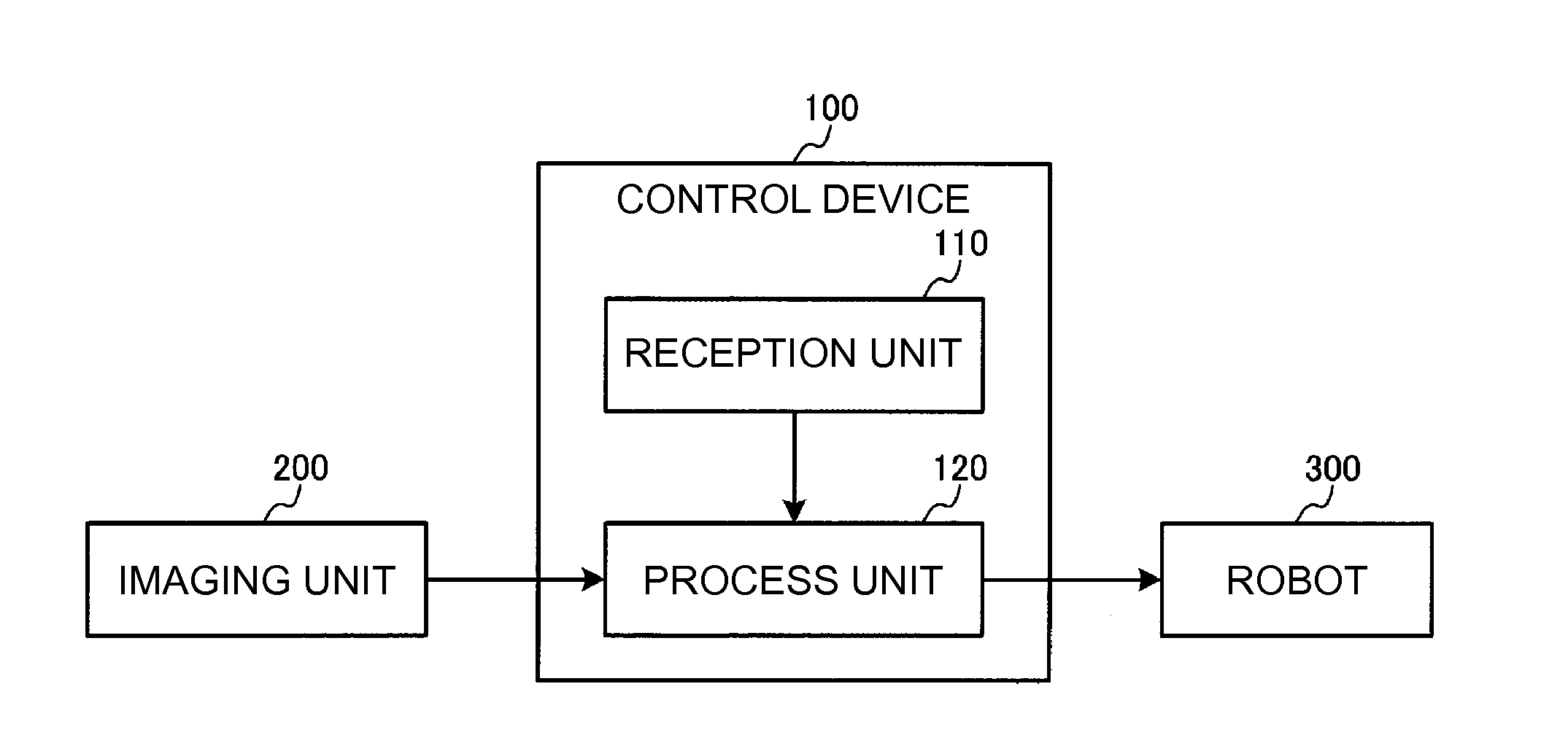
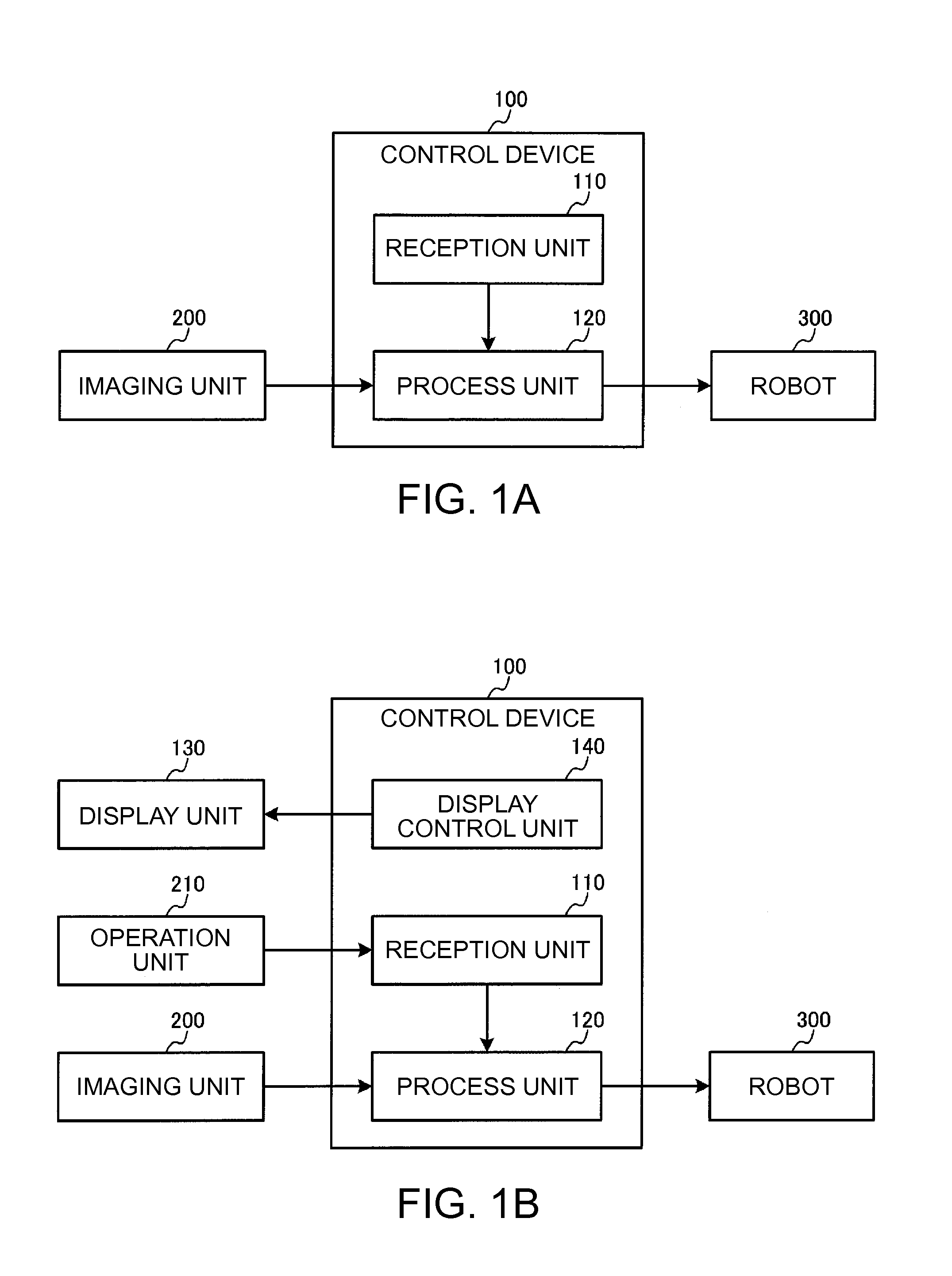
[0100]FIG. 1A illustrates a first configuration example of a control device that controls a robot using a control method of the embodiment. The first configuration example of a control device 100 will be described with reference to FIG. 1A. The first configuration example of the control device 100 includes a reception unit 110 and a process unit 120.

[0101]The reception unit 110 receives first operation information, and second operation information different from the first operation information. For example, the reception unit 110 receives the first operation information and the second operation information which are input by a user. Alternatively, the control devi...


PUM


Abstract

A control device includes a reception unit that receives first operation information and second operation information different from the first operation information; and a process unit that instructs a robot to execute operations based on the first operation information and the second operation information using a plurality of captured images of an imaged target object, the images being captured multiple times while the robot moves from a first posture to a second posture different from the first posture.

Description

BACKGROUND[0001]1. Technical Field[0002]The present invention relates to a control device, a robot, a robot system, and a control method.[0003]2. Related Art[0004]Attention is paid to an assembly robot as production equipment that can handle small volumes of production in great varieties. For example, the assembly robot may execute an operation of inserting a part with a plurality of legs, for example, a capacitor, into an electronic substrate. It is necessary to determine a procedure in which the legs are inserted into the electronic substrate, when executing the insertion operation of the part with a plurality of legs.[0005]JP-A-2013-154446 discloses a method of determining a procedure in which the plurality of legs are inserted into the electronic substrate, for example, a method of acquiring data of allowable deformation amount regarding each fitting leg of a first workpiece, and inserting the fitting leg of the first workpiece into a fitting hole of a second workpiece based on ...

Claims


Application Information

Patent Timeline
IPC IPC(8): B25J9/16
CPCB25J9/1697Y10S901/30Y10S901/47B25J9/1687G05B2219/40031
Inventor MOTOYOSHI, MASAKIONDA, KENJIKAWADA, HIROYUKIINAZUMI, MITSUHIRO
Owner SEIKO EPSON CORP
Features
  • Generate Ideas
  • Intellectual Property
  • Life Sciences
  • Materials
  • Tech Scout
  • Unparalleled Data Quality
  • Higher Quality Content
  • 60% Fewer Hallucinations
Learn More