to provide a camera including a pop-up strobe in which the strobe can be popped up utilizing the power of a barrel-driving motor, and the barrel can reliably move between a shooting position and a retracted position.
As described above, it is preferable to reduce the movement amount of the barrel between the retracted position and the shooting position in order to make the camera thinner. However, if the moving amount from retracted position to the shooting position is reduced, there is an adverse possibility that a sufficient moving amount for pop-up action cannot be obtained. Thereupon, the barrel is further advanced forward from the shooting position to increase the moving amount, and the pop-up action is carried out utilizing this moving amount. Thereafter, the barrel is retracted to the shooting position to bring the camera into the shootable state. If the pop-up mechanism of the strobe is provided with appropriate engaging / disengaging means so that the power caused by the retracting action to the shooting position of the barrel is not transmitted the strobe by the action of the engaging / disengaging means in a state in which the pop-up is completed, the flash light-emitting unit maintains the irradiating position. The flash light-emitting unit is biased in a pop-down direction by the biasing means, the action of the engaging / disengaging means is released halfway through the retracting movement of the barrel to the retracted position, this biasing force is applied to the flash light-emitting unit, and the flash light-emitting unit is brought to the accommodated position. With this arrangement, the pop-up and pop-down action can reliably be carried out.
As described above, it can be biased against the flash light-emitting unit by the biasing means but in this case, it is always biased, and, when a coil spring is utilized, for example, there is an adverse possibility that a desired action cannot be obtained because of fatigue. If, however, the power is accumulated at the time of pop-up action, the desired action is not prevented from being obtained by the fatigue even if the power accumulating means comprises a coil spring because the coil spring is usually in its natural length state. Further, since the pop-down action is carried out by the accumulated power, the pop-down action can be carried out irrespective of the moving amount of the barrel. Even if the distance between the retracted position and the shooting position is shortened for reducing the thickness of the camera, the pop-down action can reliably be carried out. The moving amount of the barrel can be reduced to a minimum by combining the invention of the fourth aspect with the second or the third aspect.
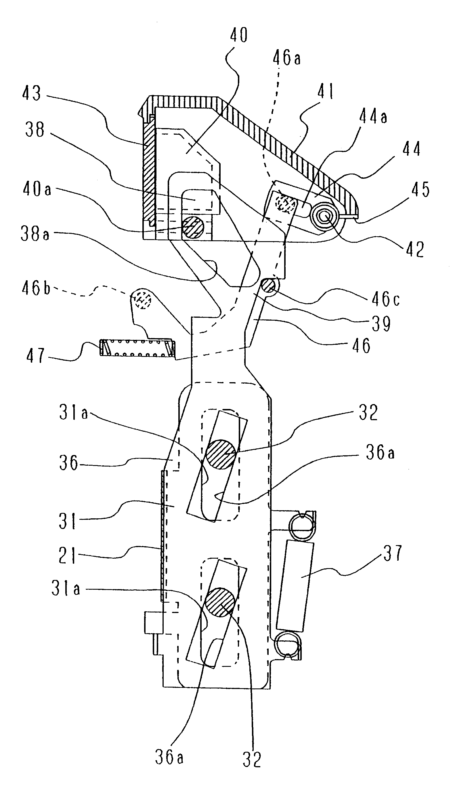
According to a fifth aspect of the invention, the camera further comprises a pair of interrupting power transmitting elements which are provided in the pop-up power transmitting path, and which are capable of relatively move and mutually transmitting a moving power, non-interference means for
cutting a transmission of the moving force between the pair of interrupting power transmitting elements, and moving-preventing means for preventing a second interrupting power transmitting element of the pair of interrupting power transmitting elements disposed closer to the flash light-emitting unit from moving in a predetermined direction, wherein the power accumulating means is interposed between the pair of interrupting power transmitting elements, when a first interrupting power transmitting element disposed closer to the power branching means is moved from its original position to a second position in a normal direction, the second interrupting power transmitting element is moved from its original position to a second position, and the flash light-emitting unit is moved to the irradiating position, the second interrupting power transmitting element is prevented from moving toward the original position by the moving-preventing means in a state in which the second interrupting power transmitting element is in the second position. The power accumulating means accumulates power by moving the first interrupting power transmitting element from the second position to a first position in the opposite direction, a moving-preventing operation of the moving-preventing means is acting, a movement of the first interrupting power transmitting element from the first position to the second position transmitted to the second interrupting power transmitting element by the non-interference means, a restraint of the second interrupting power transmitting element by the moving-preventing means is released by moving the first interrupting power transmitting element from the first position toward the original position in the opposite direction, thereby allowing the second interrupting power transmitting element to move, the flash light-emitting unit is moved to the accommodated position by the power accumulating means, in a state in which the first interrupting power transmitting element and the second interrupting power transmitting element are in their original positions, the barrel is in the retracted position, and the flash light-emitting unit is in the accommodated position, and the camera is brought into a shootable state when the first interrupting power transmitting element is in the first position.
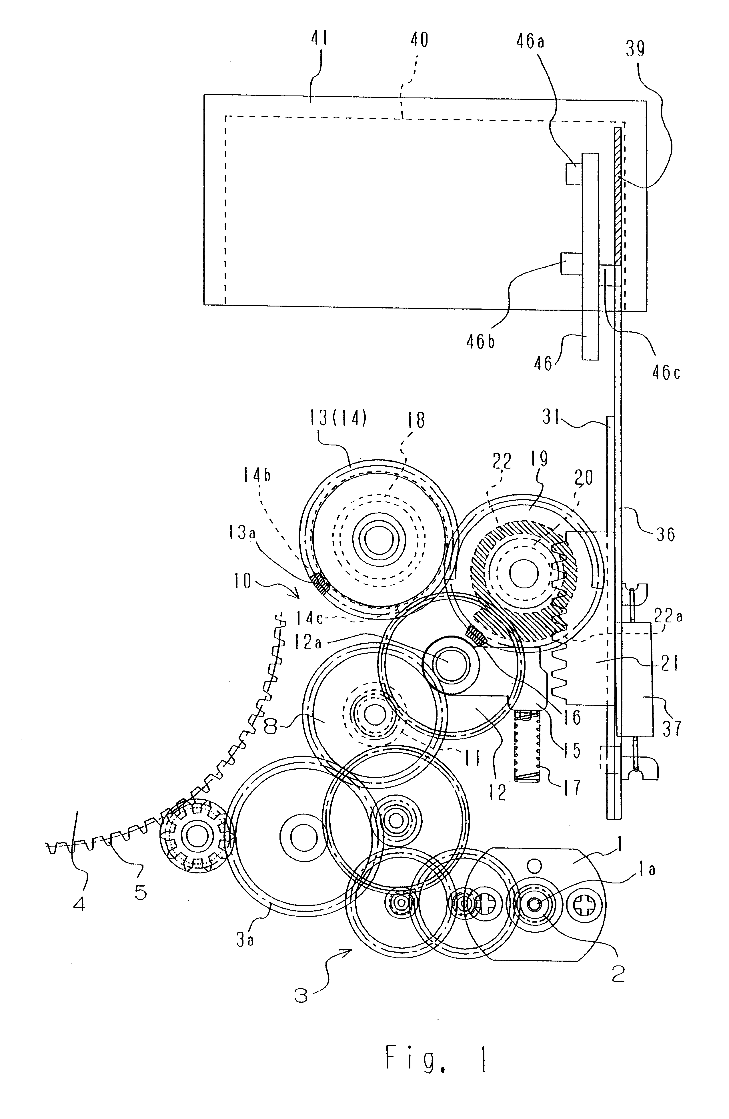
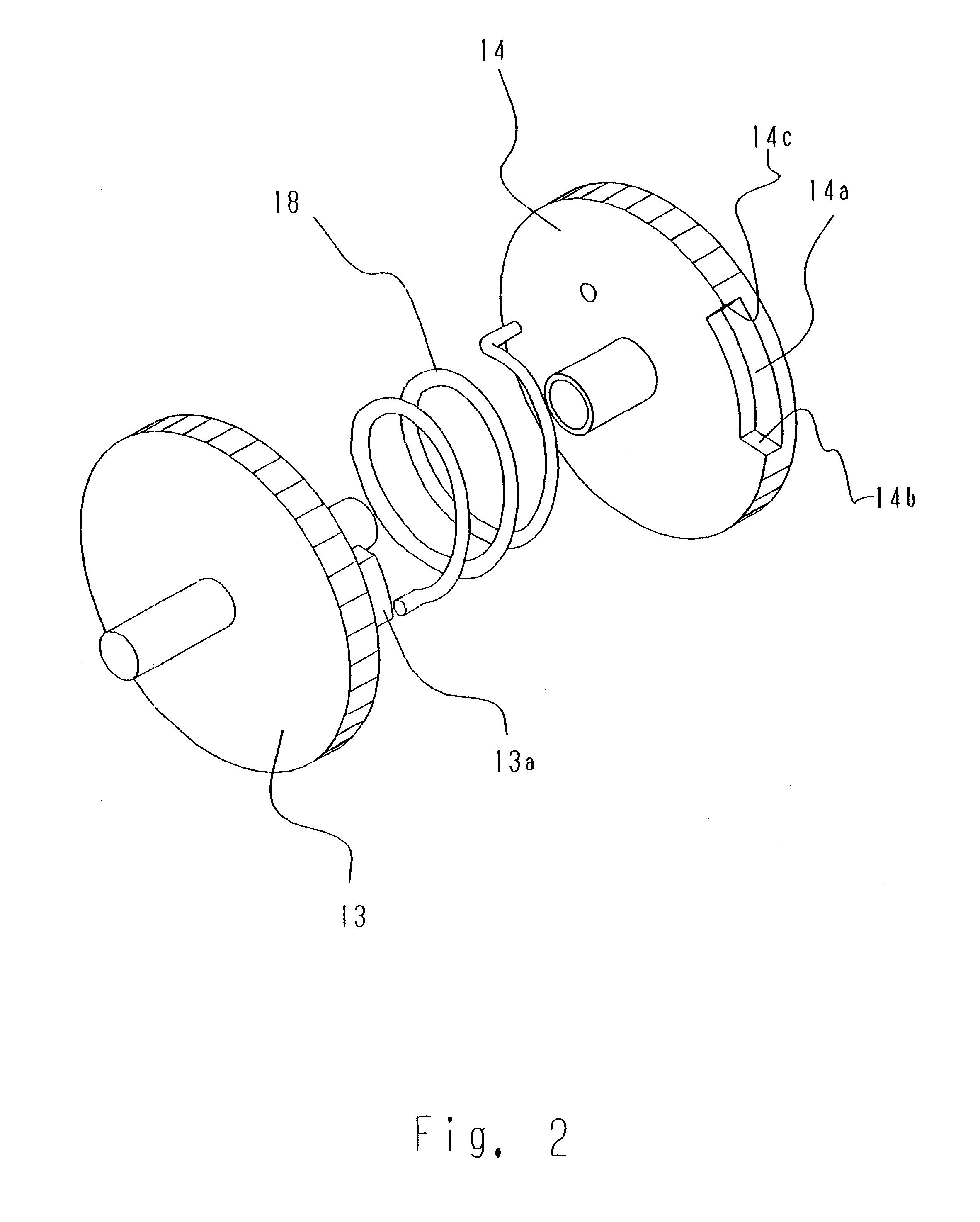
According to a sixth aspect of the invention, the pair of interrupting power transmitting elements comprise power transmitting elements which are capable of turning mutually and coaxially. That is, the interrupting power transmitting elements may be capable of mutually sliding straight but, when the barrel-power transmitting path comprises a
gear train, the rotating force is obtained from the power branching means. Therefore, in order to transmit this rotating force to the driving mechanism of the pop-up mechanism efficiently, it is preferable that the pop-up power transmitting path also comprises a
gear train. When this structure is employed, it is preferable that the interrupting power transmitting element can also turn because the structure is simplified, and if the transmitting element can turn, the installation space is reduced, which is advantageous for reducing the camera in size.
According to a tenth aspect of the invention, there is provided a pop-up method of a strobe of a camera having a pop-up strobe, wherein a retracting action for moving a barrel between a retracted position and a shooting position by a
power output from a driving source is carried out, a pop-up action for moving a flash light-emitting unit from an accommodated position to an irradiating position is carried out in synchronization with the moving action of the barrel, when the barrel is moved to a shooting position, the barrel is advanced slightly from the shooting position, the flash light-emitting unit is moved to the irradiating position with this advancing action and then, the barrel is retracted to the shooting position. When the camera is brought into the shootable state, the barrel moves beyond the shooting position. The strobe can reliably pop up by this moving distance. Thereafter, if the barrel is moved to the shooting position, the camera can be used for shooting in a state in which the strobe is popped up.
