Door sealing system

a sealing system and door technology, applied in the field of door sealing systems, can solve the problems of insufficient pressure equalizing openings for appropriate ventilation of rooms, inability to use seals in low- or zero-energy houses with controlled ventilation, and insufficient sound protection and light glimmers in one room, etc., to achieve the effect of increasing the renewal of air

Inactive Publication Date: 2015-05-07
PLANET GDZ
View PDF4 Cites 10 Cited by
  • Summary
  • Abstract
  • Description
  • Claims
  • Application Information

AI Technical Summary

Benefits of technology

[0010]It is therefore an object of the invention to permit an increased renewal of air in rooms without having an adverse effect on the freedo

Problems solved by technology

However, these seals cannot be used in low- or zero-energy houses with controlled ventilation, in particular in Minergie® houses.
As a result, however, there is no sound protection and light glimmers from one room into the other.
However, said pressure equalizing openings are sometimes insufficient for appropriate ventilati

Method used


Image

  • Door sealing system
  • Door sealing system
  • Door sealing system

Examples


Embodiment Construction

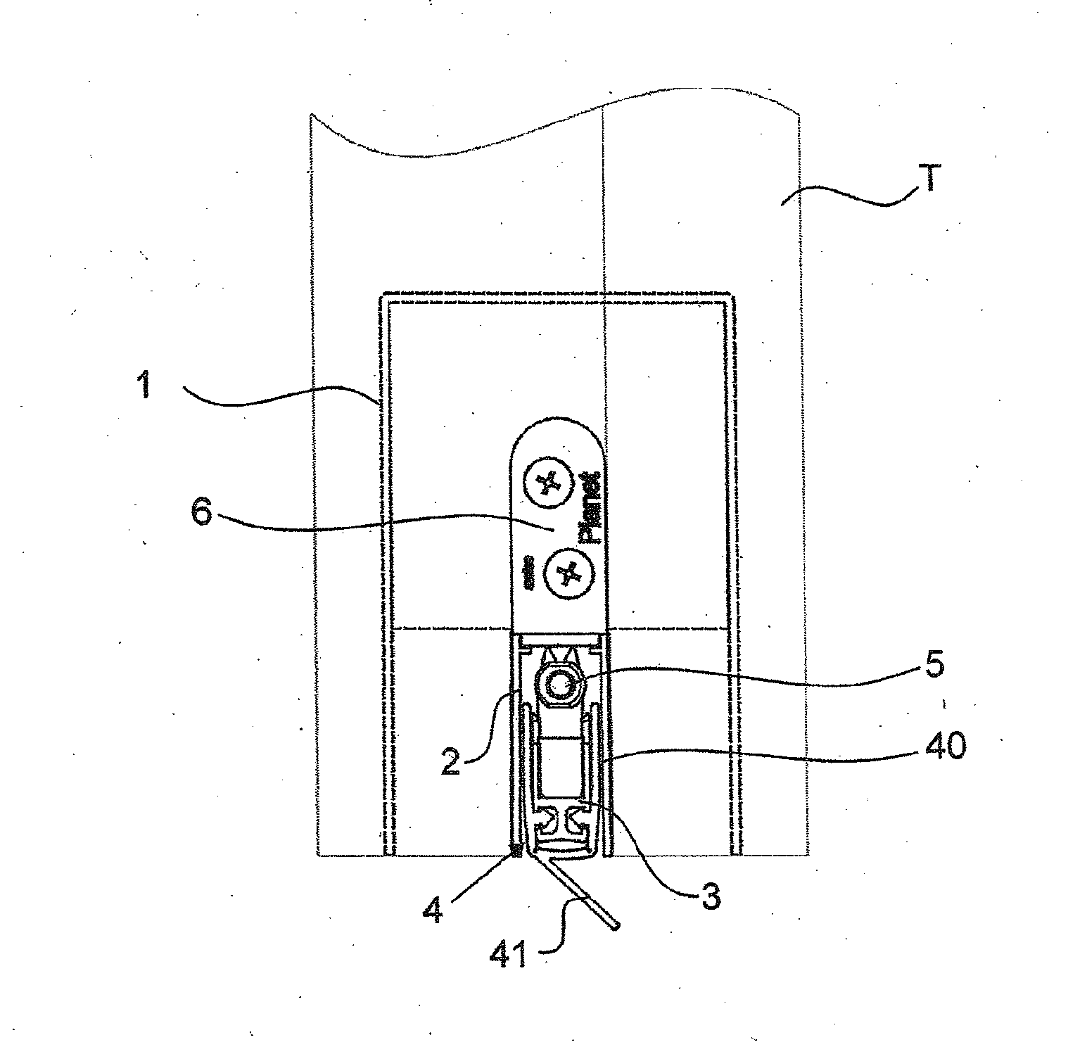
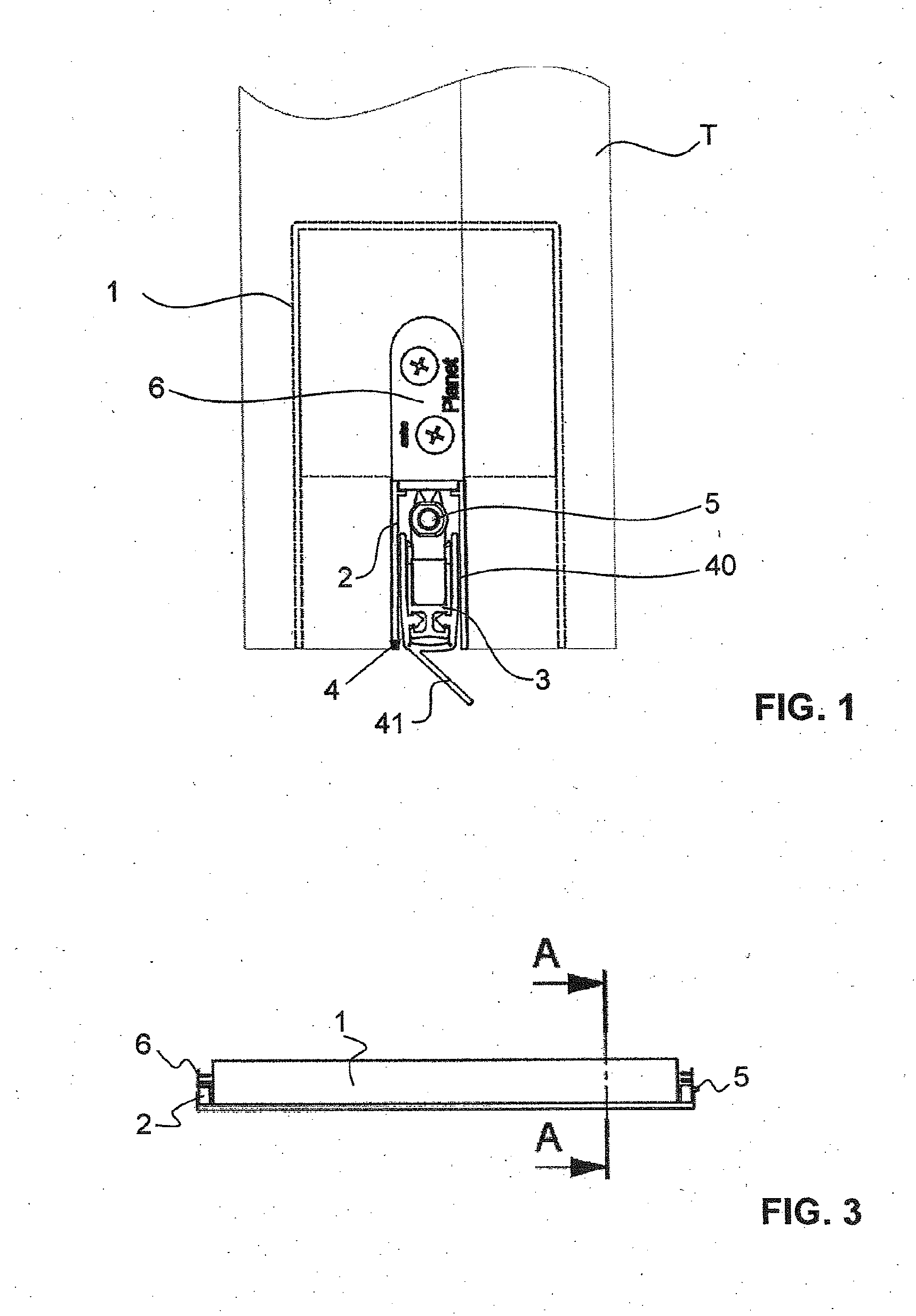
[0047]FIGS. 1 to 6 illustrate a first exemplary embodiment of the door sealing system according to the invention.

[0048]According to FIG. 1, said door sealing system is fastened in a groove N which is present in a lower edge of a door wing T. The door sealing system can alternatively also be arranged on an upper end edge, on a lateral surface of the door wing T or on a lower or upper end surface of the door wing T.

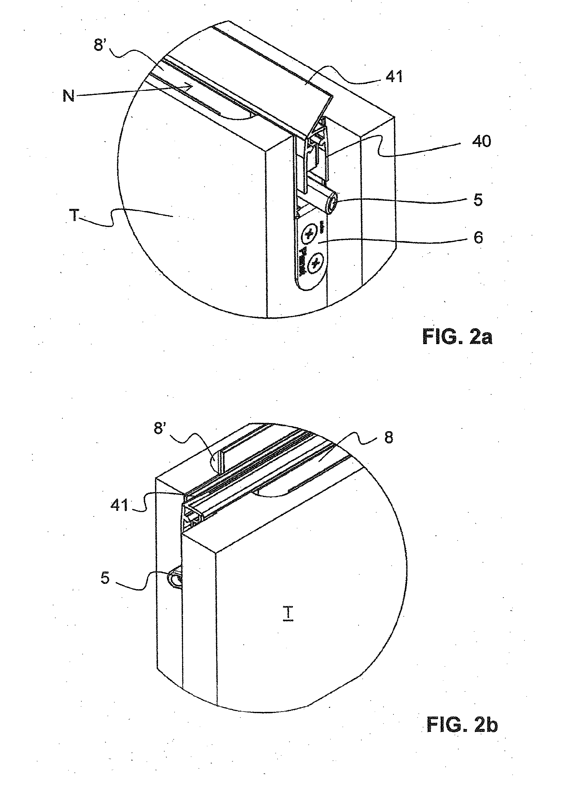
[0049]As can be seen in FIGS. 2a and 2b, the U-shaped groove N is of stepped or offset design. At at least one, preferably at both lateral ends of the groove N, the latter is designed to be narrower and less deep than in the central region. However, the groove N can also have a width and depth which are constant over its entire length.

[0050]The door sealing system is fastened to or in the door wing T by known means. In particular, there can be an outer housing 1 which receives all of the parts of the door sealing system and is of cap-shaped design with limbs parallel to the...


PUM


Abstract

The invention relates to a door sealing system comprising a door seal (2, 3, 4) for sealing an upper and a lower side of a building door leaf (T), and an air channel (8, 8′, 70) which enables, when the door seal is in the sealing position, air to circulate from a longitudinal side of the door seal (2, 3, 4) to an opposite longitudinal side of the door seal (2, 3, 4). Said door sealing system also comprises at least one ventilator (7) which guides air through said air channel (8, 8′, 70). Said inventive door sealing system enables sufficient air to be exchanged even when the door is closed.

Description

TECHNICAL FIELD[0001]The present invention relates to a door sealing system.PRIOR ART[0002]Door seals are used in regions where sound protection and draft protection are desired. They are also intended to provide a lighttight seal. Simple door seals are what are referred to as friction seals, the sealing lip or brush of which protrudes downward over a lower end surface of the door wing.[0003]Furthermore, lowerable door seals are known, which door seals customarily substantially consist of a housing in the form of a downwardly open, U-shaped profile rail, a sealing strip which is held in said housing and is displaceable relative thereto and has a sealing element, and a drive mechanism for lowering or for raising the sealing strip. The sealing strip is customarily lowered automatically when the door is closed by a force acting on an actuating rod in the longitudinal direction and setting the mechanical lowering mechanism into operation. However, it is also possible to provide a manual...

Claims


Application Information

Patent Timeline
IPC IPC(8): E06B7/20E06B7/28E06B7/02E06B5/20E06B5/10
CPCE06B7/20E06B5/20E06B5/10E06B2007/202E06B7/28E06B2007/023E06B7/02E06B7/215
Inventor DINTHEER, ANDREAS
Owner PLANET GDZ
Why Eureka
Try Eureka