Sliding window installation structure including door guide frame having separable segment structure

a sliding window and installation structure technology, applied in the direction of door/window fittings, wing accessories, wing arrangements, etc., can solve the problems of generating frictional noise, affecting the safety of passengers, so as to reduce the open view through the sliding window, the effect of reducing the open view is minimized, and the cross-section is enlarged

Active Publication Date: 2015-05-07
FILOBE
View PDF14 Cites 27 Cited by
  • Summary
  • Abstract
  • Description
  • Claims
  • Application Information

AI Technical Summary

Benefits of technology

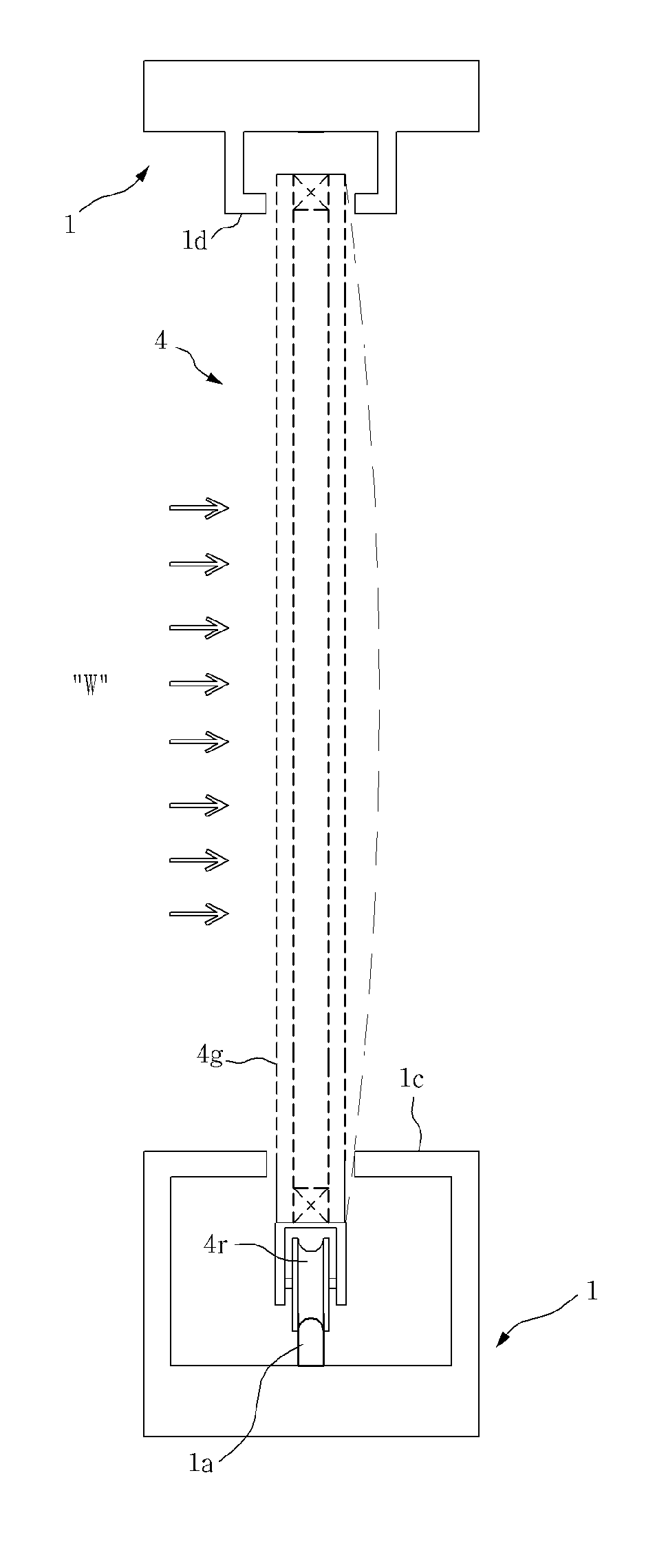
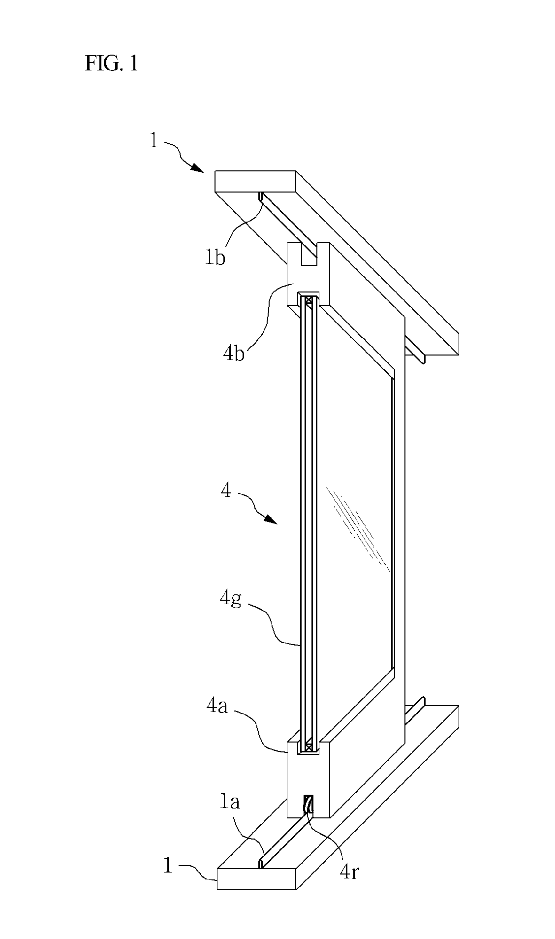
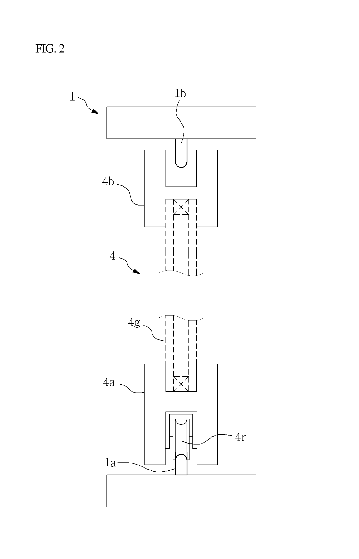
[0030]According to the present invention, since the glass panel forming the sliding window constituting the sliding window system is directly mounted on the roller member to be supported without a separate quadrilateral door sash that supports the glass panel forming the sliding window, a phenomenon of reducing an open view through the sliding window can be minimized. Since the vertical stiffeners having an enlarged cross-section (cross-section having a thickness thicker than the glass panel) are rigidly joined to the opposite side surfaces of the glass panel supported by the roller, the transverse bending rigidity of the glass panel can be reinforced to exhibit high wind pressure resistance. Further, the sliding window is configured to be installed inside of the door guide frame to be integrally installed in a state in which the sliding window is provided with the vert...

Problems solved by technology

In such a case, the sliding window 4 is slid in the state where the glass panel 4g and one side surface of the lower pocket guide 1c are in contact with each other, thereby generating frictional noise as well as seriously damaging mobility.
In such a case, there is a strong likelihood that the glass panel may be destroyed.
However, when the separation distances e and e′ increase, the resistance against the wind pressure is weakened.
However, in such a case, structural instability in relation to the wind pressure is caused due to the excessive separation distance e and there is a considerable disadvantage in hermeticity.
However, such an installation structure also has a problem in that the door guide frame and the roller guide rail included therein protrude upward fro...

Method used


Image

  • Sliding window installation structure including door guide frame having separable segment structure
  • Sliding window installation structure including door guide frame having separable segment structure
  • Sliding window installation structure including door guide frame having separable segment structure

Examples


first embodiment

[0038]FIGS. 15 to 17 are cross-sectional views illustrating a sliding window installation structure in according to the present invention which conventional axial type rollers are used, and an operating state thereof.

second embodiment

[0039]FIGS. 18 to 21 are views illustrating a sliding window installation structure according to the present invention in which annular roller devices are used for a sliding window, and an operating state thereof.

[0040]FIGS. 22 to 27 are plan views illustrating in sequence a process of removing pocket guide segments from a door guide frame body and removing a sliding window provided with a vertical stiffener from a window frame in a sliding window installation structure according to the present invention.

[0041]FIG. 28 is a plan view illustrating an operating state of an embodiment using pocket guide segments divided unlike the embodiment illustrated in FIGS. 22 to 27.

[0042]FIG. 29 is a plan view illustrating a plan view for describing an additional characteristic structure for improving heat insulation in the sliding window installation structure according to the present invention and an effect thereof, and FIG. 30 is a plan view illustrating a comparative embodiment from which the ...


PUM


Abstract

The present invention relates to a door guide frame for guiding the sliding movement of a roller device which supports a sliding window and provides a sliding opening/closing operation and, more specifically, to a sliding window installation structure which: stably supports and moves a sliding window on a bottom surface and an upper surface on which the sliding window is installed; reduces an installation space by minimizing the size of a door guide frame and a roller device for supporting a heavy sliding window, thereby obtaining a wider open view when applied to a window; enables vertical stiffeners having an expanded cross section (cross section thicker than glass) for compensating a transverse bending rigidity of glass to be connected to both sides of the glass which constitutes the sliding window formed by including the glass that is supported by a roller; and enables the sliding window with the vertical stiffeners to be installed within the door guide frame in an integrated manner and the sliding window to be detached from the door guide frame in which the sliding window includes the vertical stiffeners.

Description

TECHNICAL FIELD[0001]The present invention relates to a door guide frame for guiding the sliding movement of a roller device which supports a sliding window and provides a sliding opening / closing operation and, more particularly, to a sliding window installation structure which is capable of: stably supporting and moving a sliding window or a horizontal sliding window (hereinafter, generally referred to as a “sliding window”) on a bottom surface and a top surface on which the sliding window is installed; reducing an installation space by minimizing the size of a door guide frame and a roller device for supporting a heavy sliding window, thereby obtaining a wider open view when applied to a window; and employing a structure which prevents a door guide rail from protruding upward from the bottom surface of a window frame so as to prevent occurrence of a passage obstacle which may be caused when the door guide rail protrudes on a moving passage while the window is opened, as well as to...

Claims


Application Information

Patent Timeline
IPC IPC(8): E05D15/06E05D15/48E06B7/22E06B3/46
CPCE05D15/0678E05D15/0621E06B7/22E05D15/0686E05D15/48E06B3/4609E05D15/0665E05D15/0682E05Y2600/56E05Y2800/406E05Y2900/148E06B3/26347E06B3/4681E06B2003/5463E05D13/00E05D15/06E06B3/46
Inventor LEE, KWANG-SEOK
Owner FILOBE
Why Eureka
Try Eureka