Pitot tube designs for compressible and incompressible fluid flow with viscosity and turbulence

a technology of fluid flow and viscosity, applied in the direction of fluid speed measurement, speed/acceleration/shock measurement, instruments, etc., can solve problems and achieve the effects of high viscosity, high viscosity, and affecting the performance of the devi

Inactive Publication Date: 2015-05-07
WILLARD JR HAROLD JAMES
View PDF4 Cites 4 Cited by
  • Summary
  • Abstract
  • Description
  • Claims
  • Application Information

AI Technical Summary

Benefits of technology

[0036]This invention presents Pitot tube designs and methodology for determining the flow characteristics of incompressible and compressible fluids in subsonic and supersonic flow which include the effects of viscosity and turbulence in the analysis. Pitot tubes and other flow measuring devices now based on differential pressure-velocity relationships assume either an inviscid fluid or a fluid having an unrealistically high viscosity (Poiseuille fluid) in the analyses and calibration of their performance. Furthermore, the effect of turbulence on flow behavior is not considered, which can greatly affect the performance of the device.
[0037]In the present invention, a methodology, called the Two-Fluid Theory, is developed and supported by experimental data, which treats a real fluid as being composed of a mixture of two ideal fluids: an inviscid fluid and a fluid having a very high viscosity (Poiseuille fluid). The resulting expressions for flow velocity in pipes are applicable to real fluids of any viscosity and to tubes of any length-to-diameter ratio, including entrance effects, for subsonic or supersonic flow. Additionally, the effect of turbulence is included in the analysis.
[0038]The methodology is applied to Pitot tube designs comprising smooth bore hollow tubes of length 10 cm and internal diameter 0.5 cm, opened at one end to fluid fields in either subsonic or supersonic flow; connected to a pressure measuring device at the opposite end to measure total pressure; surrounded by an annulus of 0.25 cm differential radius, sealed at both ends and connected to a pressure measuring device to measure static pressure; made of stainless steel, titanium, or other metal or material appropriate for the fluid being measured; tube walls are insulated for supersonic, compressible fluid flow to achieve adiabatic conditions and length of the annulus is abbreviated to minimize heat loss (to 4 cm); small bore holes are positioned around the circumference of the annuli. and 1 cm from the flow entrance in accordance with the new methodology to ensure that the viscous component of the flow is fully established; temperature measuring devices can be positioned at the static and total pressure measuring stations to confirm that adiabatic conditions are met for compressible fluid flow, which are not required for the device used for incompressible fluid flow since isothermal conditions are satisfactory, rendering Pitot tubes for such applications much simpler to fabricate, operate and maintain.

Problems solved by technology

Furthermore, the effect of turbulence on flow behavior is not considered, which can greatly affect the performance of the device.

Method used


Image

  • Pitot tube designs for compressible and incompressible fluid flow with viscosity and turbulence
  • Pitot tube designs for compressible and incompressible fluid flow with viscosity and turbulence
  • Pitot tube designs for compressible and incompressible fluid flow with viscosity and turbulence

Examples


Embodiment Construction

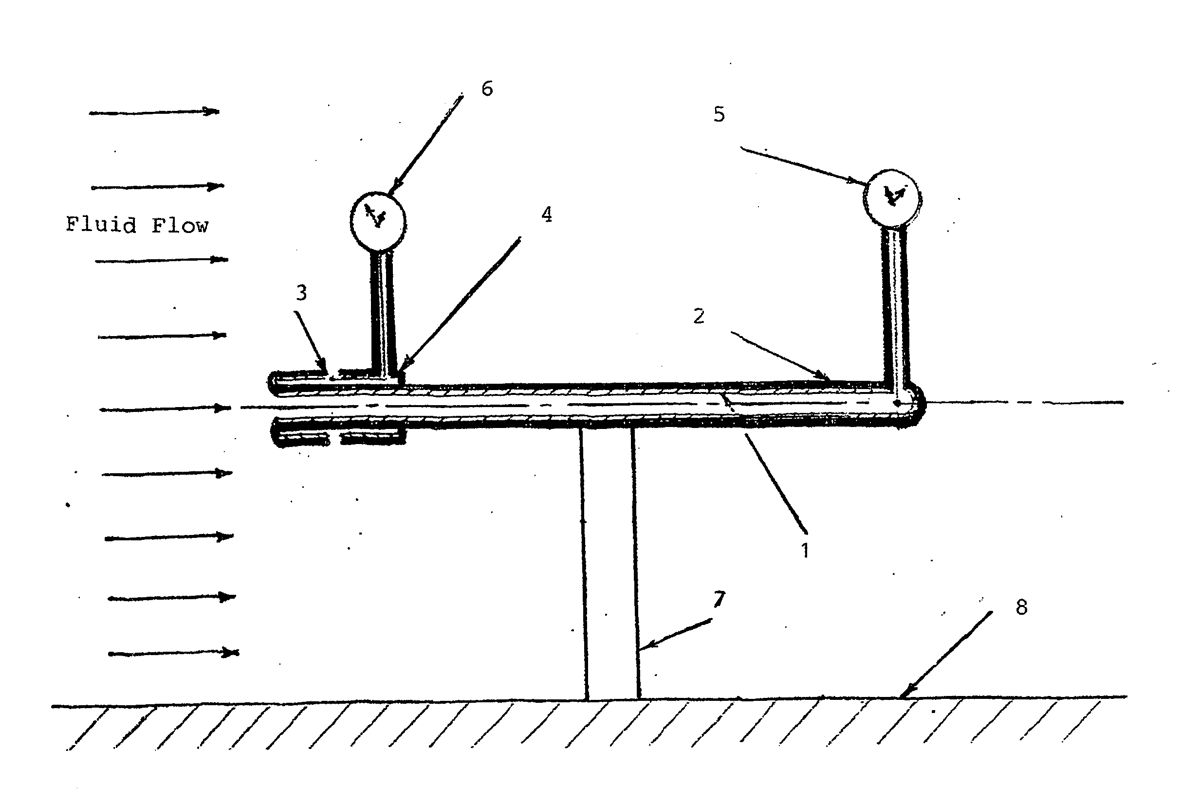
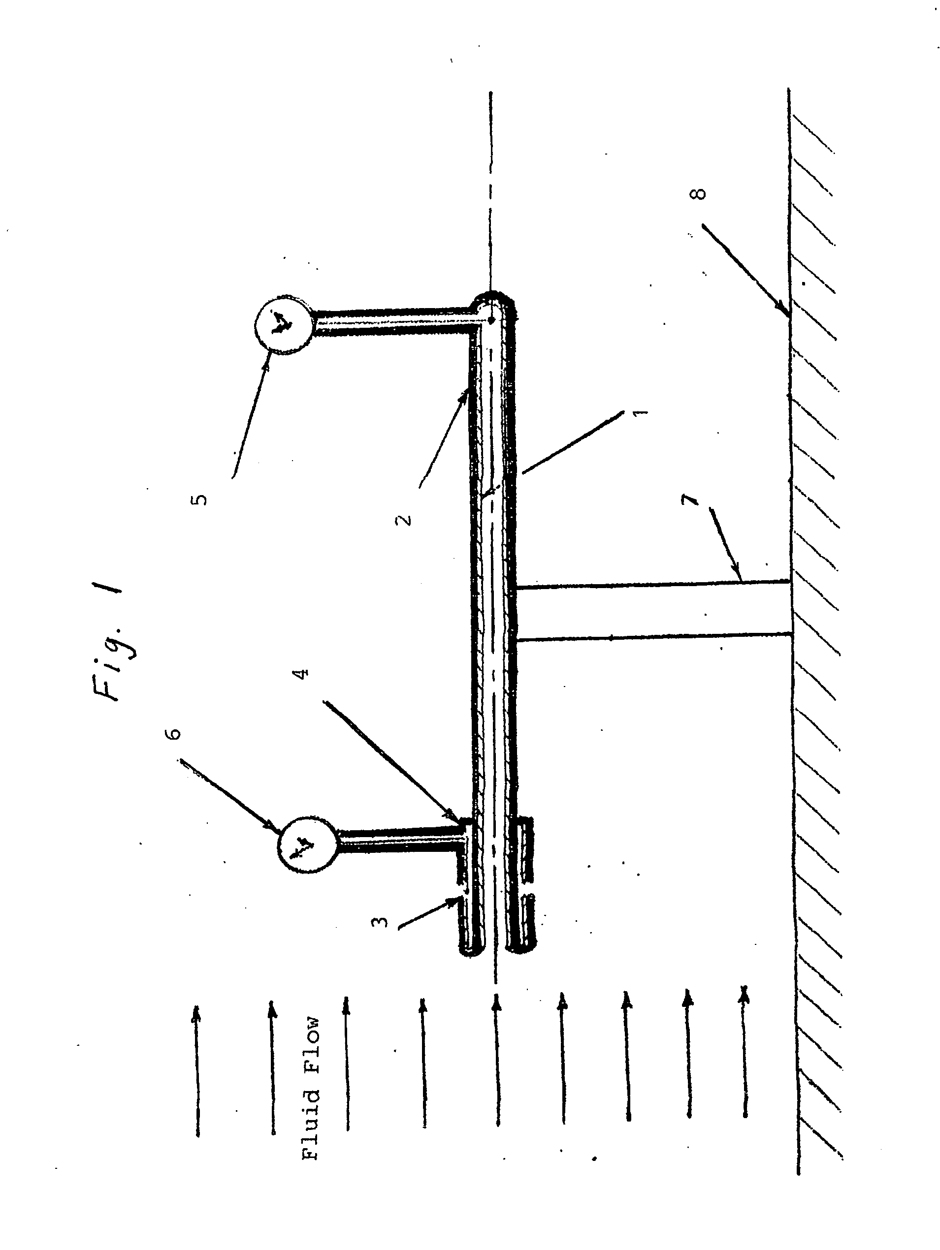
[0039]FIG. 1 is a schematic of a Pitot tube conforming to this invention, which is to be manufactured in accordance with current practice from a smooth tube (1) of steel, titanium, or other metal or material selected for the environment in which the device is to be employed. The schematic shows the Pitot tube affixed to a support (7) attached to a surface (8), which could be the surface of an aircraft, land or water vehicle, or the inside of a pipe or conduit, or anyplace else where Pitot tubes are employed.

[0040]The fluid direction is shown parallel to the axis of the tube. If the fluid impinges at an angle θ to the tube, the component of the velocity along the tube axis, V.cos θ, is to be applied in the analysis in lieu of V.

[0041]The length of support (7) is such that disturbance of the flow due to proximity of the wall is not significant.

[0042]The Pitot of FIG. 1 is intended for compressible fluid flow into the supersonic flow regime and is insulated to achieve adaibatic conditi...


PUM


Abstract

This invention presents a Pitot tube design and methodology for determining the flow characteristics of fluids in subsonic and supersonic flow, including the effects of viscosity and turbulence. A new methodology, the Two-Fluid Theory, is developed which treats a real fluid as being composed of two ideal fluids: an inviscid fluid and a Poiseuille fluid. The resulting expression for flow velocity is applicable to a real fluid of any viscosity and to pipes of any L/D ratios, including entrance effects.
Two designs, comprising annular, smooth-bore tubes, with devices for measuring total and static pressures, are presented: one for incompressible flow; one for compressible, supersonic flow. Allowance is made for the viscous component of the flow to become fully developed, in accordance with the Theory.

Description

BRIEF DESCRIPTION OF THE FIGURES[0001]FIG. 1. Schematic of pitot tube insulated for compressible, supersonic fluid flow.[0002]FIG. 2. Measured Saybolt viscometer results (Ref. 2): Time to drain 60 cc of fluid through a capillary tube as a function of kinematic viscosity; calculations from Two-Fluid Theory with and without turbulence.[0003]FIG. 3. Measured fluid height in a tank draining through a smooth tube of diameter 0.35 cm and length 16.7 cm as a function of time for water and olive oil at approximately room temperature. Curves are Two-Fluid Theory calculations with and without turbulence and for water as an inviscid fluid.[0004]FIG. 4. Calculated fluid velocities from Two-Fluid Theory and from using inviscid fluid expression for air at 12,000M and at standard temperature and pressure as a function of differential Pitot tube pressure (L=10 cm; Le=1 cm; a=0.25 cm).[0005]FIG. 5. Calculated fluid velocities from Two-Fluid Theory for water and for a fluid having a density of water ...

Claims


Application Information

Patent Timeline
Patent Type & Authority Applications(United States)
IPC IPC(8): G01F1/46
CPCG01F1/46G01P5/165
Inventor WILLARD, JR., HAROLD JAMES
Owner WILLARD JR HAROLD JAMES
Why Eureka
Try Eureka