Sliding component

a technology of sliding components and components, applied in the direction of engine seals, engine components, mechanical devices, etc., can solve problems such as mass leakage, and achieve the effect of reducing the pressure acting on the sealing fa

Active Publication Date: 2015-05-07
EAGLE INDS
View PDF12 Cites 40 Cited by
  • Summary
  • Abstract
  • Description
  • Claims
  • Application Information

AI Technical Summary

Benefits of technology

[0029]The present invention has excellent effects as described below:
[0030](1) Extremely shallow grooves constituting a Rayleigh step mechanism are provided in a manner facing the high-pressure fluid side of the sealing face, while deep fluid-introduction grooves for introducing the high-pressure fluid are provided on the upstream side of the extremely shallow grooves in a manner continuing to the high-pressure fluid side, and accordingly high-pressure fluid is actively introduced to the upstream side of the extremely shallow grooves in the circumferential direction via the deep fluid-introduction grooves, and consequently the decompression that would otherwise occur as the fluid flows into the extremely shallow grooves is suppressed and cavitation is prevented as a result. In addition, should any deposit be produced in the extremely shallow grooves or any deposit or other foreign matter enter the grooves, such foreign matter would be discharged from the extremely shallow grooves toward the high-pressure fluid side instead of remaining in the extremely shallow grooves and causing leakage.
[0031](2) The number of negative steps (steps from the higher surface to the lower surface) that cause cavitation can be controlled by setting the number of extremely shallow grooves as deemed appropriate.
[0032](3) Circular deep pressure-reduction grooves are provided in a manner facing the low-pressure fluid side of the extremely shallow grooves and deep fluid-introduction grooves, for separating the extremely shallow grooves and deep fluid-introduction grooves from the sealing face on the low-pressure fluid side and thereby reducing the pressure acting upon the sealing face on the low-pressure fluid side, and accordingly the extremely shallow grooves where dynamic pressure generates are separated from the sealing face S on the low-pressure fluid side of the extremely shallow grooves and deep fluid-introduction grooves, and consequently the fluid pressure acting upon the sealing face on the low-pressure fluid side is reduced to roughly equivalent to the pressure on the high-pressure fluid side and the amount of fluid leaking toward the low-pressure fluid side can be reduced as a result.
[0033](4) Circular pumping grooves acting to push back toward the high-pressure fluid side the fluid that tends to leak from the high-pressure fluid side toward the low-pressure fluid side are provided on the sealing face facing the low-pressure fluid side, and consequently the fluid that tends to leak from the sealing face toward the low-pressure fluid side can be reduced.
[0034](5) Circular pumping grooves acting to push back toward the high-pressure fluid side the fluid that tends to leak from the high-pressure fluid side toward the low-pressure fluid side are provided on the sealing face facing the low-pressure fluid side of the deep pressure-reduction grooves, and accordingly the high-pressure fluid side of the pumping grooves has no wall to prevent the fluid that tends to leak toward the low-pressure fluid side from being pushed back toward the high-pressure fluid side, even when the pumping grooves are provided on the surfaces of circular extremely shallow steps that are lower than the sealing face, and consequently sufficient pumping effect can be demonstrated and leakage toward the low-pressure fluid side can be prevented as a result.

Problems solved by technology

However, Prior Art 1 presents a problem in that, regardless of the rotating direction, the dynamic-pressure generation grooves and concave / convex parts constituted by fine grooves are arranged in pairs in order to generate dynamic pressure and improve lubrication performance, and therefore cavitation always occurs at the negative step (step from the higher surface to the lower surface) between each pair of grooves during operation, which means that when this prior art is used as a mechanical seal for automotive water pumps, the constituents of sealed fluid may deposit onto, attach to, and accumulate on the sealing face due to cavitation, potentially leading to massive leakage.

Method used


Image

  • Sliding component
  • Sliding component
  • Sliding component

Examples


embodiment 1

[0048]A sliding component pertaining to Embodiment 1 for carrying out the present invention is explained by referring to FIGS. 1 to 3.

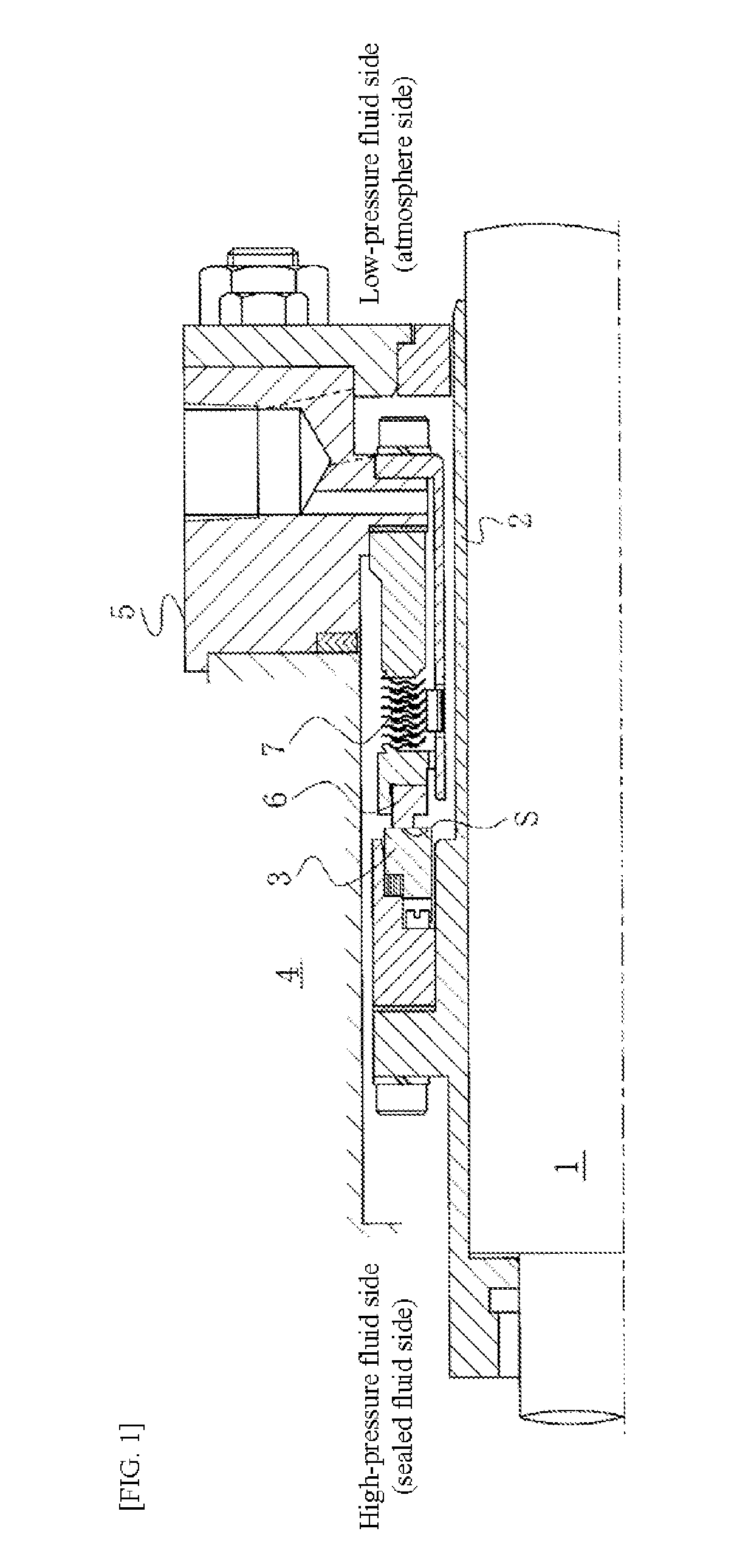
[0049]FIG. 1 is a front section view showing an example of a mechanical seal for general industrial machinery.

[0050]The mechanical seal in FIG. 1 is of the inside type, which is the type that seals the high-pressure fluid (sealed fluid) that tends to leak from the outer periphery to the inner periphery of the sealing face, comprising: a circular rotating ring 3 that constitutes one sliding part provided via a sleeve 2 on a rotational axis 1 for driving a pump impeller (not illustrated) on the high-pressure fluid side (sealed fluid side) in a manner rotatable together with the rotational axis 1; and a circular stationary ring 6 that constitutes the other sliding part provided on a seal cover 5 fixed on a pump housing 4 in a manner not rotatable but movable in the axial direction, wherein the sealing faces S of the two that have been mirror-surface-fini...

embodiment 2

[0064]The sliding component pertaining to Embodiment 2 of the present invention is explained by referring to FIGS. 4 and 5.

[0065]Embodiment 2 is different from Embodiment 1 in that deep pressure-reduction grooves are added, but the remainder of the constitution is the same as in Embodiment 1 and therefore the same members also used in Embodiment 1 are denoted by the same symbols and are not explained redundantly.

[0066]In FIG. 4, circular deep pressure-reduction grooves 15 are provided on the sealing face of the stationary ring 6 having the extremely shallow grooves 10 and deep fluid-introduction grooves 11, in a manner facing the low-pressure fluid side of the extremely shallow grooves 10 and deep fluid-introduction grooves 11, for separating the extremely shallow grooves 10 and deep fluid-introduction grooves 11 from the sealing face on the low-pressure fluid side and thereby reducing the pressure acting upon the sealing face on the low-pressure fluid side. The deep pressure-reduct...

embodiment 3

[0070]The sliding component pertaining to Embodiment 3 of the present invention is explained by referring to FIGS. 6 and 7.

[0071]Embodiment 3 is different from Embodiment 2 in that circular pumping grooves are provided on the sealing face facing the low-pressure fluid side of the deep pressure-reduction grooves, but the remainder of the constitution is the same as in Embodiment 2 and therefore the same members also used in Embodiment 2 are denoted by the same symbols and are not explained redundantly.

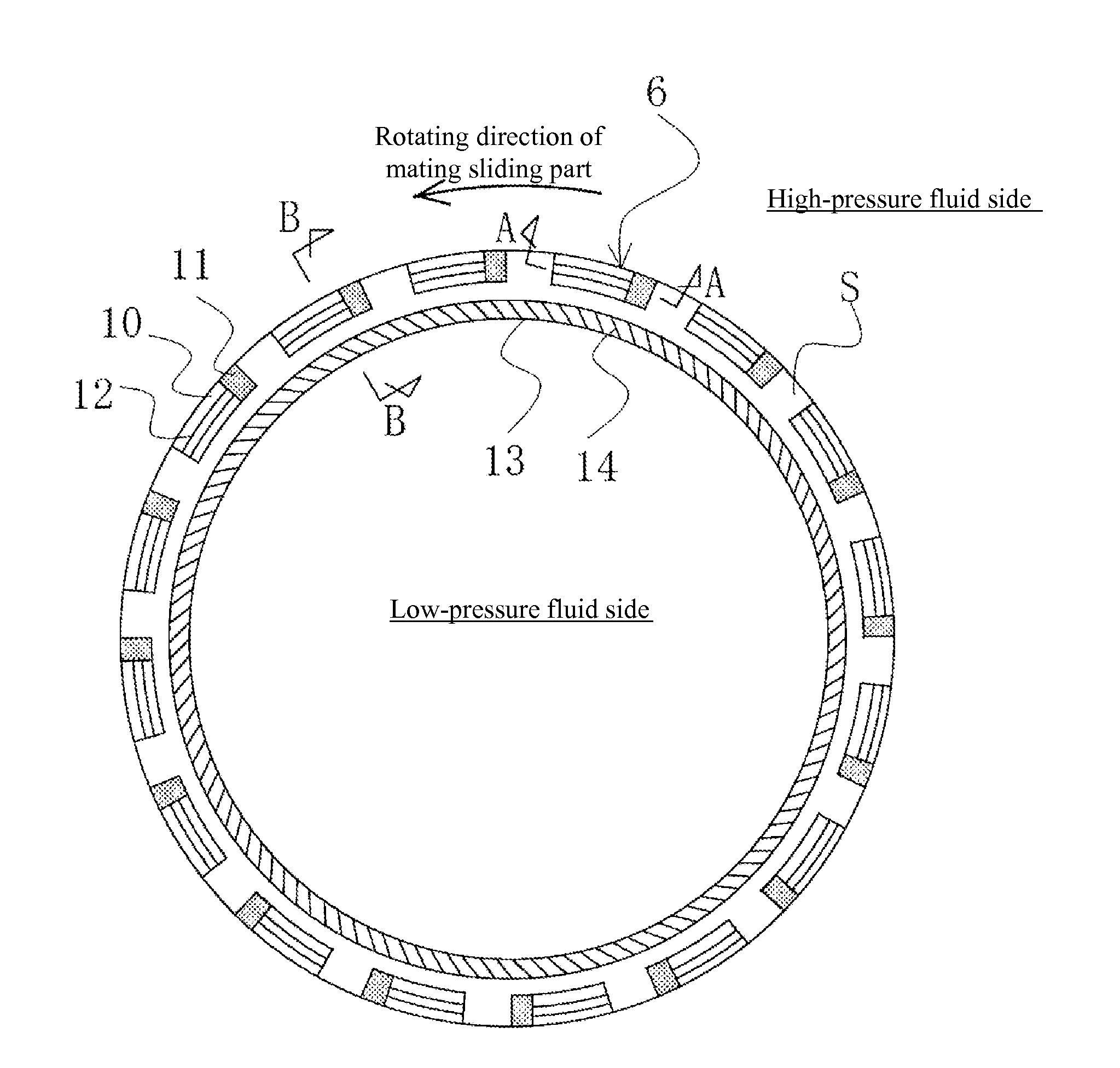
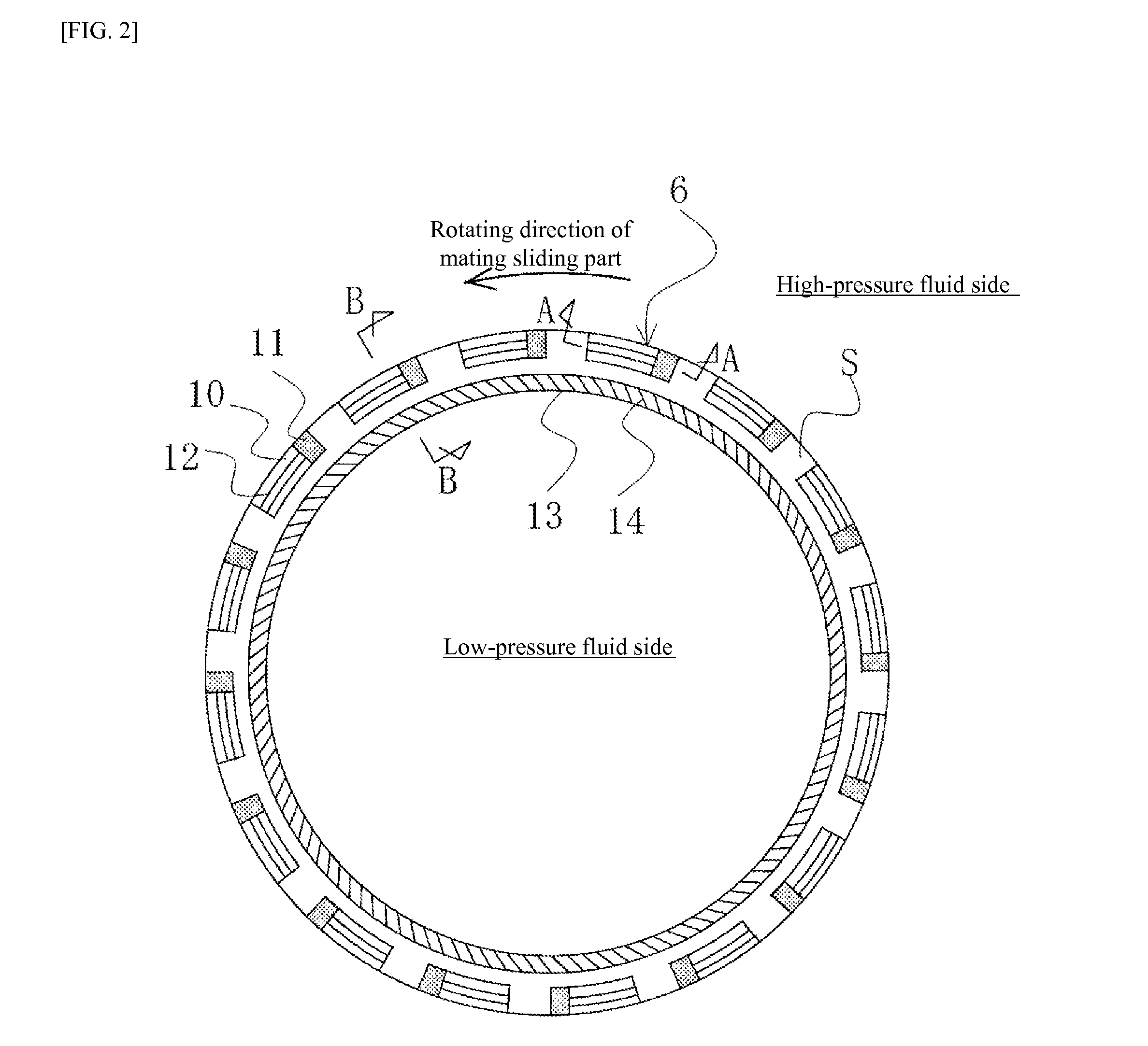
[0072]In FIG. 6, the circular pumping grooves 14 are provided not on the sealing face S facing the low-pressure fluid side as in Embodiments 1 and 2, but they are provided on the sealing face S facing the low-pressure fluid side of the deep pressure-reduction grooves 15. Also, ideally, the pumping grooves 14 are provided on the surfaces of circular extremely shallow steps 13 that are lower than the sealing face S, as in Embodiments 1 and 2.

[0073]As shown in FIG. 7, when the pumping groo...


PUM


Abstract

A sliding component, which achieves both sealing and lubrication by preventing cavitation from occurring in the dynamic-pressure generation mechanism and thereby solving the problem of leakage that will otherwise result from such cavitation, is characterized in that, on a sealing face of one of a pair of sliding parts that slide against each other, extremely shallow grooves constituting a Rayleigh step mechanism are provided in a manner facing the high-pressure fluid side of the sealing face, while deep fluid-introduction grooves for introducing the high-pressure fluid are provided on the upstream side of the extremely shallow grooves in a manner continuing to the high-pressure fluid side.

Description

TECHNICAL FIELD[0001]The present invention relates to a sliding component suitable for mechanical seals, bearings and other sliding mechanisms, for example. In particular, the present invention relates to a sliding component for seal rings, bearings, etc., that must reduce friction by retaining a fluid on the sealing face and also prevent the fluid from leaking from the sealing face.BACKGROUND ART[0002]For a mechanical seal, which is an example of sliding component, to maintain sealing property for a long period of time, it must satisfy the mutually exclusive conditions of “seal” and “lubricate.” Particularly in recent years, the demand for lower friction is increasing further in the area of environmental protection, etc., as a means to prevent the sealed fluid from leaking while reducing mechanical loss at the same time. One way to reduce friction is to generate dynamic pressure between the sealing faces by means of rotation to create the so-called fluid lubrication state where the...

Claims


Application Information

Patent Timeline
Patent Type & Authority Applications(United States)
IPC IPC(8): F16J15/34
CPCF16J15/3412F16J15/3424
Inventor ITADANI, MASATOSHITOKUNAGA, YUICHIRO
Owner EAGLE INDS
Why Eureka
Try Eureka