Magnetic core element, magnetic core module and an indictive component using the magnetic core module

Active Publication Date: 2015-05-07
SUMIDA COMPONENTS & MODULES
View PDF0 Cites 20 Cited by
  • Summary
  • Abstract
  • Description
  • Claims
  • Application Information

AI Technical Summary

Benefits of technology

[0006]Against this backdrop it is an object of the invention to provide a magnetic core element which is suited for the cost-efficient production of bendable, respectively, very long rod core antennae with little magnetic leakage. It is furthermore an object of the prese

Problems solved by technology

Therefore, the core of these antennae may be subjected to stress, resulting in altered magnetic properties if the deformation is too strong, as great tensile forces and compressive forces occur in the material in the layer levels.
Moreover, the basis materials of these so-called tape cores are significantly more expensive than those for ferrite cores, and the magnetic losses of more inexpensive, iron-based amorphous cores, as compared to ferrites, are clearly greater at frequencies above 100 kHz.
Conventional methods for the production of those antennae using tape cores additionally have the drawback that the stacking of the tapes is relatively complicated.
Antennae with cores made of ferrite rods that have a bent or very long shape are difficult to realize, or not at all, due to the production method.
In the production of bent or long antennae mechanical strains in the ferrite core rod itself, or external impacts, may result in the breakage of the core, and thus in a deterioration of the magnetic pro

Method used


Image

  • Magnetic core element, magnetic core module and an indictive component using the magnetic core module
  • Magnetic core element, magnetic core module and an indictive component using the magnetic core module
  • Magnetic core element, magnetic core module and an indictive component using the magnetic core module

Examples


second embodiment

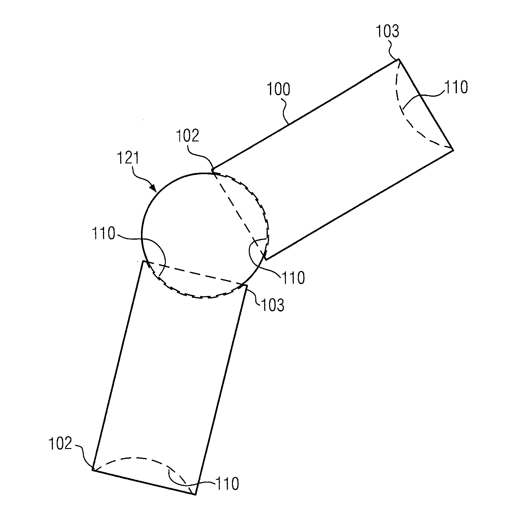
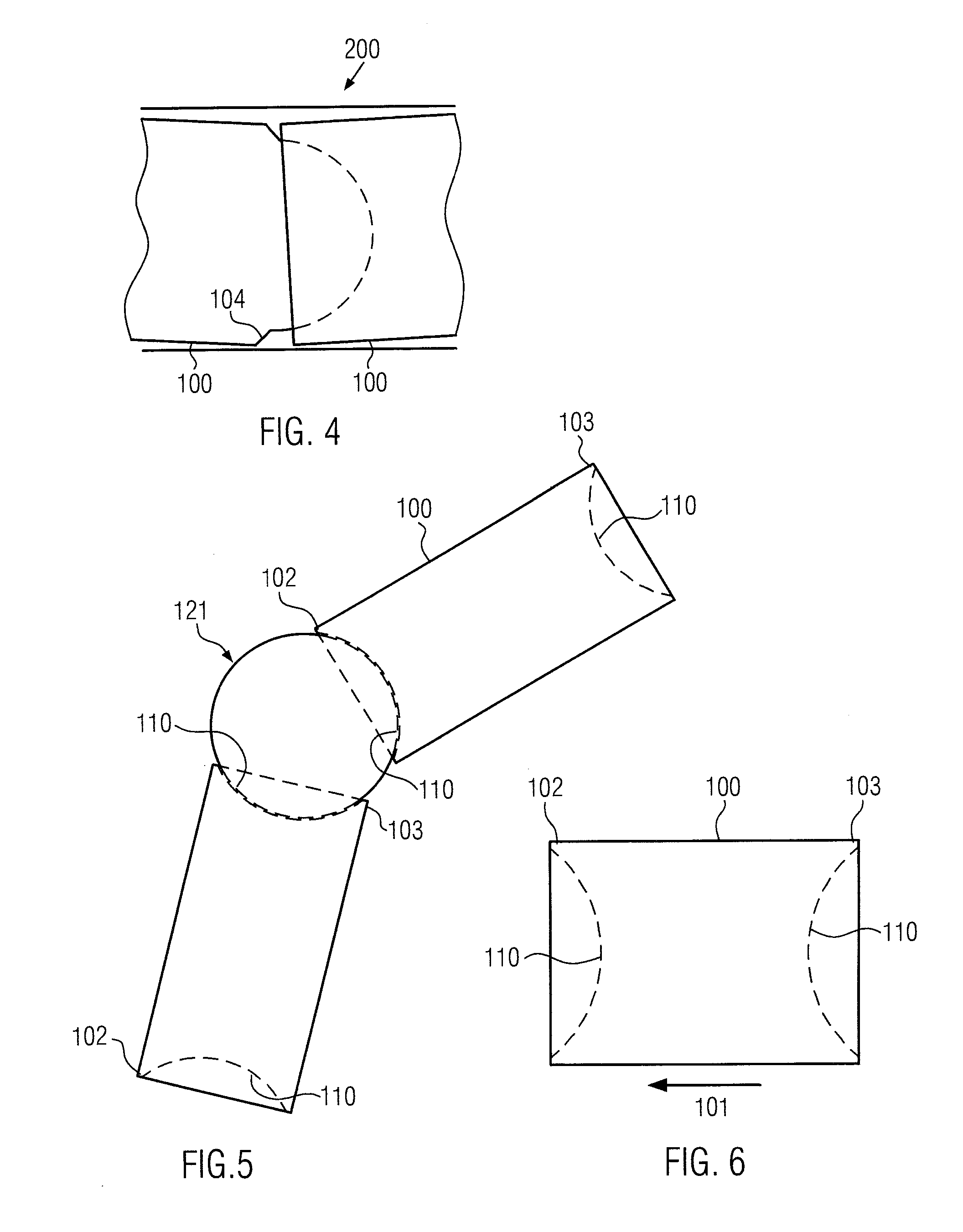
[0043]FIG. 5 shows the present invention. In this case, the magnetic core element 100 preferably has a spherical recess 110 at the first end 102 and the second end 103 respectively. A variably adjustable, bent connection of at least two of the magnetic core elements 100, each having the spherical recess 110 at the first and second ends 102, 103, is achieved by a connecting sphere 121. Thus, it is possible to realize an even greater mounting angle as compared to the sphere / cup end contour. The use of the connecting sphere, respectively, magnetic sphere 121 furthermore allows the joining of several cores to one nodal point. Thus, for example, three or four magnetic core elements 100 can be connected to one another by one magnetic sphere 121.

[0044]FIG. 6 shows a schematic view of the magnetic core element 100 of the second embodiment of the present invention, which has the spherical recess 110 at its first and second ends 102, 103 respectively. The magnetic core element 100 may further...

third embodiment

[0045]FIG. 7 shows the present invention. In this case, the magnetic core element 100, having a rod shape with a rectangular cross-section, preferably has a cylindrical recess 110 at the first end 102 and a cylindrical connecting protrusion 122 at the second end 103. This embodiment is characterized by a very flat design, along with a high magnetic cross-section.

[0046]Moreover, the rectangular cross-section may comprise a cylindrical recess 110 at the first and second ends 102, 103 respectively. A variably adjustable, bent connection of at least two of the magnetic core elements 100, each having the cylindrical recess 110 at the first and second ends 102, 103 respectively, is achieved by a cylindrical connecting piece.

[0047]FIG. 8 shows a connection of at least two magnetic core elements 100 by means of a tension spring system. In this case, each magnetic core element 100 includes a holding member 130, 131, which is preferably made of plastic, so as to connect the spherical magnetic...


PUM


Abstract

A rod-shaped magnetic core element, having a first end with a spherical or cylindrical recess or a spherical or cylindrical connecting protrusion, and a second end with a spherical or cylindrical recess or a spherical or cylindrical connecting protrusion so that a bent connection of at least two magnetic core elements is variably adjustable. Magnetic core elements comprising spherical or cylindrical magnetic core ends of this type allow a nearly gap-free construction with little magnetic leakage due to slightly larger end surfaces in comparison with ferrite rods having beveled plane end section surfaces. The enlarged end surface of the spherical surface advantageously allows a more stable connection of individual magnetic core elements without adhesive bonding. This allows the construction of flexible, multiple-member and inexpensive rod core coils and antennae.

Description

FIELD OF THE INVENTION[0001]The present invention relates to a magnetic core element, a magnetic core module and an inductive component using the magnetic core module for the construction of antennae having an improved coverage, in particular antennae for locking and unlocking a motor vehicle, and for the position detection.BACKGROUND OF THE INVENTION[0002]Wireless electronic locking and unlocking systems are known from the automobile industry. For example, magnetic antennae are installed in automobile door handles, in door frames, side panels or bumpers of motor vehicles, to transmit or receive an electromagnetic signal in order to allow a wireless communication, e.g. for communicating with a transceiver of a key. To accommodate a transmit-receive antenna in a bent door handle the magnetic core is designed, for example, as a rod core of a longitudinal shape, which is formed of several tape-shaped layers of a soft-magnetic metal alloy, wherein the bending tolerance of the layer stac...

Claims


Application Information

Patent Timeline
IPC IPC(8): H01F27/24H01F3/00
CPCH01F3/00H01F27/24H01F3/08H01F3/10H01Q7/08H01F3/14
Inventor WINKLER, JOHANN
Owner SUMIDA COMPONENTS & MODULES
Why Eureka
Try Eureka