Driving force control system for vehicle

a technology of driving force control and control system, which is applied in the direction of machines/engines, process and machine control, instruments, etc., can solve the problems of engine not being engine output being delayed inevitably, and engine being not allowed to drive at a driving point to achieve the intermediate speed, etc., to achieve the effect of enhancing the agility of the vehicle, improving fuel economy, and increasing the speed ratio

Inactive Publication Date: 2015-05-07
TOYOTA JIDOSHA KK
View PDF11 Cites 24 Cited by
  • Summary
  • Abstract
  • Description
  • Claims
  • Application Information

AI Technical Summary

Benefits of technology

[0011]Thus, according to the present invention, the engine speed is basically controlled in a manner to improve the fuel economy. However, when the acceleration is demanded, the engine speed is increased in accordance with the demand to increase the engine power. Specifically, if the driver intends to accelerate the vehicle greatly, the upper limit value of the engine speed is set to the higher value in accordance with the index representing the intension of the driver. Therefore, the driver is allowed to drive the vehicle according to his / her preference. In contrast, if the driver intends to accelerate the vehicle but not especially to enhance the agility of the vehicle, the upper limit value of the engine speed is set to the relatively lower value in accordance with the index representing the intension of the driver. In this case, therefore, the engine speed of the vehicle can be adjusted according to the driver's intention when accelerate the vehicle. In addition, the acceleration can also be established as intended so that the driver is allowed to drive the vehicle according to his / her preference.
[0012]Provided that the present invention is applied to the vehicle having the continuously variable transmission, the driving force control system changes the speed ratio stepwise, and increase the speed ratio if the driver intends to enhance the agility of the vehicle.

Problems solved by technology

However, an output of the engine is delayed inevitably to achieve the target output.
Therefore, if the driver has a desire to accelerate the vehicle abruptly, the driver may further depress the accelerator pedal to cover shortage of the engine output caused by the delay in augmentation of the engine output.
In addition, an intermediate speed between those speeds may not be set, that is, the engine may not be allowed to be driven at a driving point to achieve the intermediate speed.
Further, when the accelerating operation is carried out to accelerate the vehicle greatly, the engine speed may reach the upper limit speed irrespective of an operating amount.
Therefore, the driver may feel a delay in augmentation of the vehicle speed behind an augmentation of the engine speed.

Method used


Image

  • Driving force control system for vehicle
  • Driving force control system for vehicle
  • Driving force control system for vehicle

Examples


Embodiment Construction

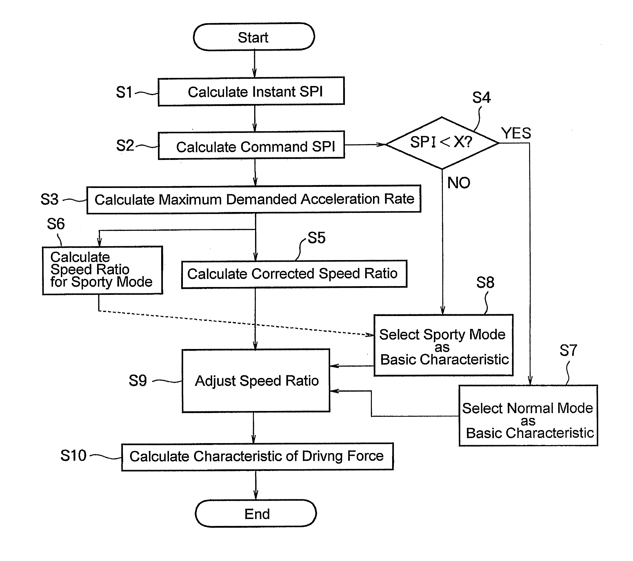
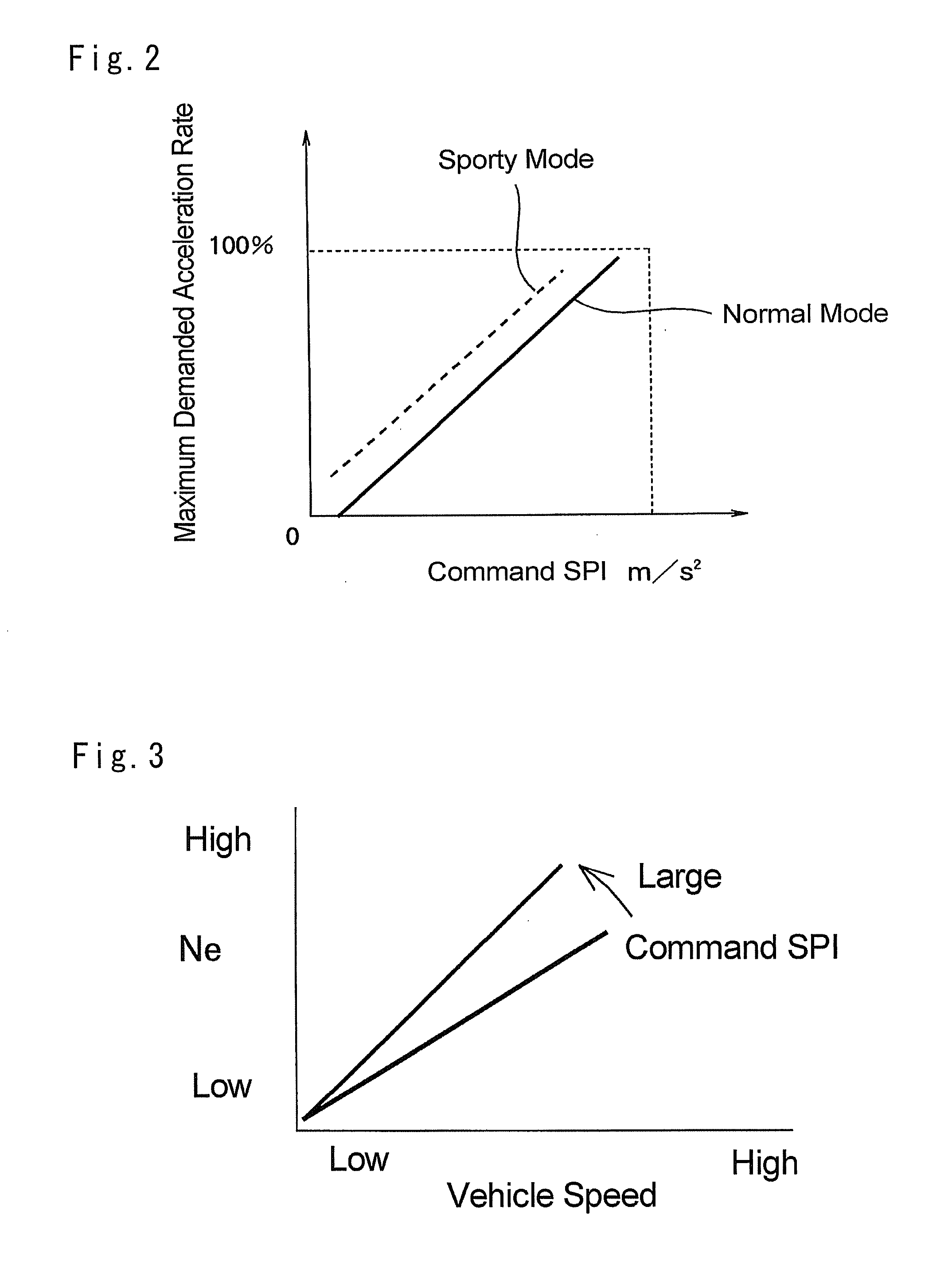
[0028]Next, preferred examples of the present invention will be explained hereinafter. The control system of the present invention is applied to a vehicle accelerated and turned by operating predetermined devices, and the vehicle is driven by an internal combustion engine or a motor. The vehicle is comprised of a mechanism for continuously changing a speed ratio as a ratio of a speed of an output shaft to a speed of the engine. Preferably, a driving mode for changing the speed ratio stepwise by a manual operation (i.e., a manual mode) can be selected in the vehicle. For example, the driving mode for changing the speed ratio stepwise can be selected in a vehicle comprised of a belt-driven continuously variable transmission or a toroidal continuously variable transmission. In addition, the driving mode for changing the speed ratio stepwise may also be selected in a hybrid vehicle comprised of an engine and a motor serving as a prime mover, and a power distribution device adapted to pe...


PUM


Abstract

A driving force control system for a vehicle having a mechanism for changing an engine speed continuously. The driving force control system basically controls said mechanism in a manner such that the engine speed is adjusted to optimize fuel economy. The driving force control system is configured to determine an index representing a demand to enhance agility of behavior of the vehicle based on an actual behavior of the vehicle or an amount of operation carried out by a driver to cause said behavior. An upper limit value of the engine speed of the case in which a drive demand is increased is determined on the basis of the index, and the upper limit value is set to the higher value with an increase in the index representing the demand to enhance agility of behavior of the vehicle.

Description

TECHNICAL FIELD[0001]The present invention relates to a control system for controlling a driving force of a vehicle, and especially to a control system for controlling a prime mover to comply with a driving preference (or intention) of a driver.BACKGROUND ART[0002]A driving force of an automobile is governed by an output of an engine with respect to an opening degree of an accelerator and a speed ratio of a transmission connected with the engine. Basically, such relation is determined according to a grade of a vehicle at a designing or planning stage. However, a required driving force differs according to a road condition, a driving preference of a driver of the vehicle and so on. Therefore, it is preferable to adjust characteristics of the driving force and the speed ratio in accordance with the road condition and the driving preference of the driver.[0003]For example, PCT international publication WO2011 / 021634 discloses a vehicle control system configured to control characteristi...

Claims


Application Information

Patent Timeline
Patent Type & Authority Applications(United States)
IPC IPC(8): B60W10/06F02D29/02B60W20/00
CPCB60W10/06F02D2700/07F02D29/02B60W20/10B60W10/11B60W30/1882B60W2710/0644B60K6/445B60W10/04B60W10/10B60W10/105B60W20/30B60W50/082B60W2540/215B60W2710/1005Y02T10/62Y02T10/84
Inventor TAKEUCHI, KEISUKEHAYASHI, TAKESHIAGATA, YOSHIMITSUTANAHASHI, TOSHIONOUMURA, SHINTSURUOKA, KAZUOKANEKO, HIROKIHONDA, TOMOYUKI
Owner TOYOTA JIDOSHA KK
Why Eureka
Try Eureka