
Foundation anchor for industrial-scale machines

a technology of industrial scale machines and foundation anchors, applied in foundation engineering, construction, building construction, etc., can solve the problems of high technical demands on components, accompanied by serious consequences, and the inability of the forces acting on the foundation anchor to be diverted into the concrete foundation without, and achieve the effect of adversity in performance-to-weight ratio

Active Publication Date: 2015-05-14
SIEMENS ENERGY GLOBAL GMBH & CO KG
View PDF8 Cites 1 Cited by
  • Summary
  • Abstract
  • Description
  • Claims
  • Application Information

AI Technical Summary

Benefits of technology

The invention relates to a foundation anchor system for machines that are used in industrial-scale operations. The system includes a foundation anchor with an anchor box and anchor rods that are connected to the anchor box through anchor sockets. The anchor rods can be prefabricated in a factory and connected to the anchor sockets only during installation on site. This saves time and enables easier handling and transportation. The foundation anchor is designed to absorb and distribute forces of at least 2000 kN, ensuring effective and safe operation of the machines in the event of malfunctions.

Problems solved by technology

The anchoring of industrial-scale machines in a concrete foundation which has been provided specifically for supporting and fastening the machine places high technical demands on the components responsible for distributing forces into the concrete foundation.
However, it proves to be disadvantageous that the forces acting on the foundation anchor cannot be diverted into the concrete foundation without the forces being redirected.
In particular in the event of operation when there is a malfunction, the forces acting on this joining area can exceed the strength of the connection, as a result of which an undesired failure, sometimes accompanied by serious consequences, can occur.
However, a disadvantage of this technical solution is that the devices need to be completely prefabricated before they are incorporated into the concrete foundation.
The length and the weight of the connecting bars consequently entails a high degree of handling and transportation complexity.
However, this alignment can only be achieved with great technical effort because two heavy and elongated components have to be welded together.
Moreover, the high forces which need to be transmitted require the anchor box and connecting bars to be welded together very carefully, which cannot be performed on site when the device is being installed in a concrete foundation but typically needs to be carefully prefabricated in a factory.
Furthermore, such a symmetrical arrangement ensures that excess stresses in the foundation anchor are avoided, which results in a generally lower likelihood of failure.
Furthermore, because of such local eccentricities, there could also be a greater likelihood of the foundation anchor failing when very high loads are distributed.

Method used


Image

  • Foundation anchor for industrial-scale machines
  • Foundation anchor for industrial-scale machines
  • Foundation anchor for industrial-scale machines

Examples


Embodiment Construction

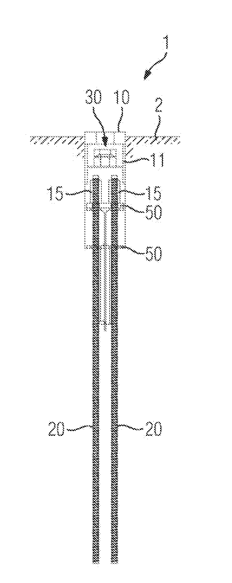
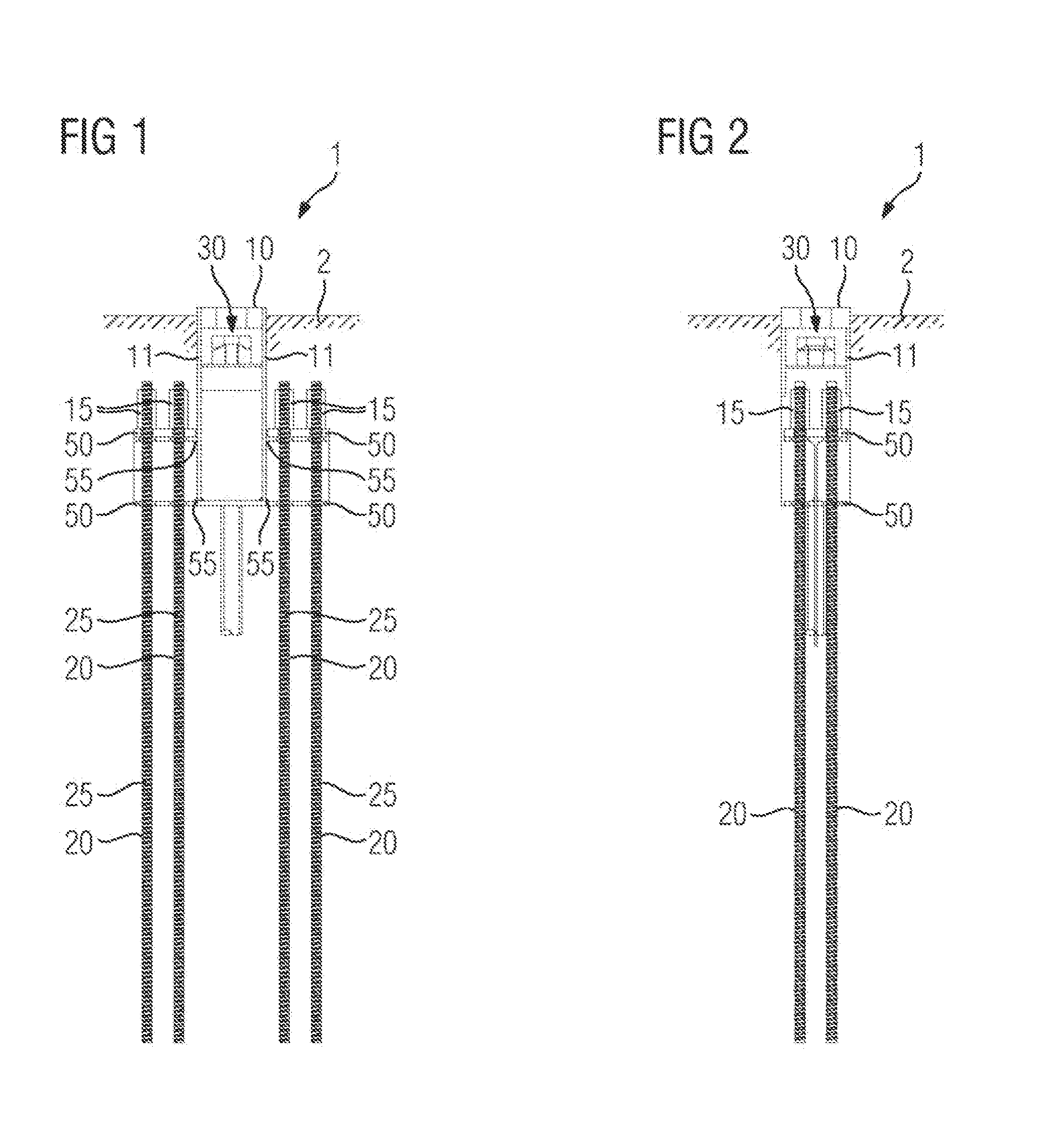
[0057]FIG. 1 shows a side view in section through a bond between a foundation anchor 1, as known, and a concrete foundation 2. The foundation anchor 1 comprises an anchor box 10 which is largely embedded, together with eight anchor rods 20, in the concrete foundation 2. The anchor box 10 has two side walls 11 which are in each case connected to two crossbeams 50. The side wall 11 is connected to the crossbeam 50 in each case in a joining area 55. The side wall 11 is hereby welded to a crossbeam 50 with a right-angled arrangement being formed.

[0058]In order to fasten a fastening bolt 110 (not shown in further detail) of an industrial-scale machine 100 (not shown) in the foundation anchor 1, the latter has a fastening section 30 which is surrounded by the side walls 11.

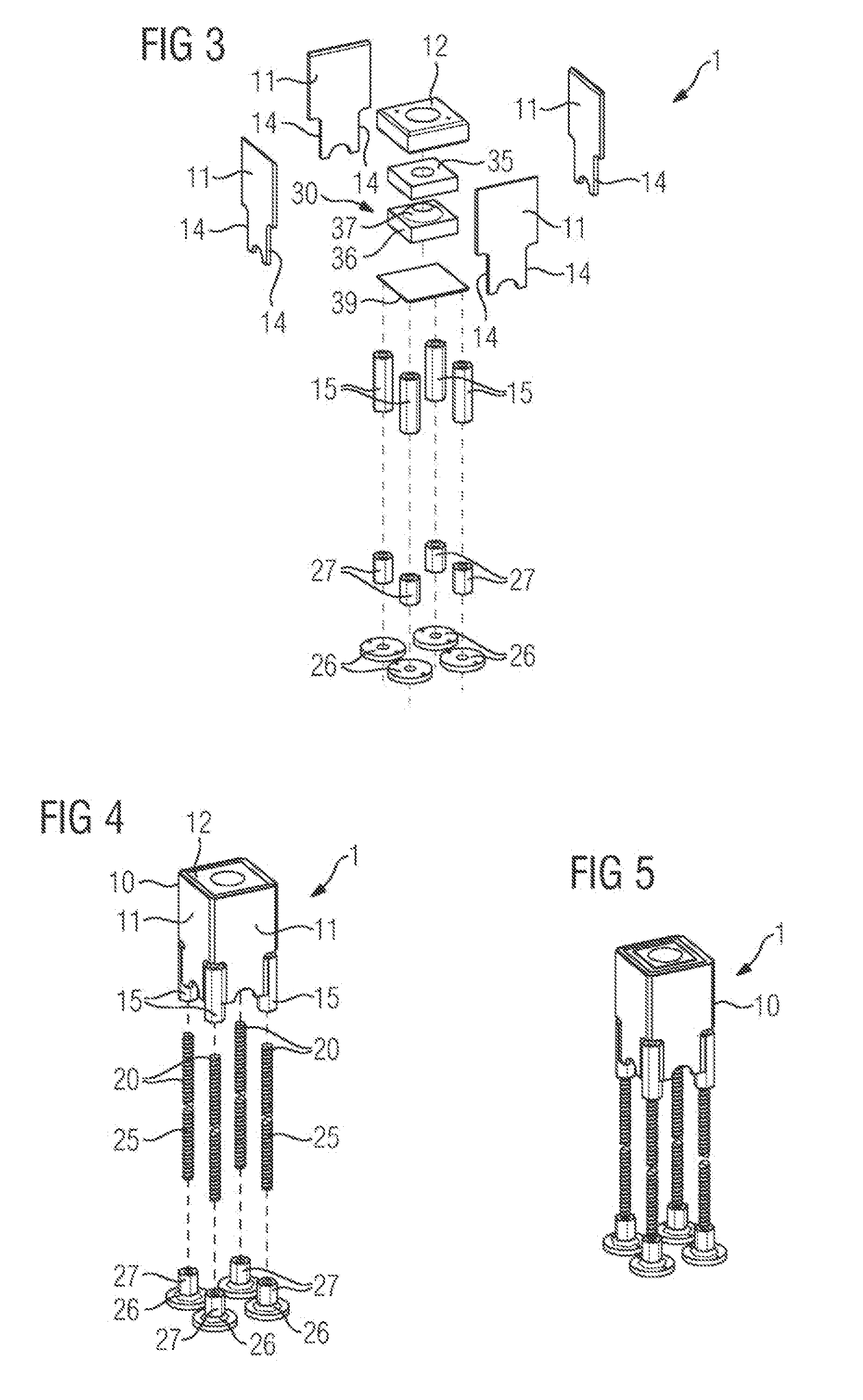
[0059]In order to anchor the foundation anchor 1 in the concrete foundation 2, in all eight anchor rods 20 are provided which have suitable threaded ribs 25. The anchor rods 20 are screwed into suitable anchor sockets 1...


PUM


Abstract

A foundation anchor for forcefittingly anchoring an industrial-scale machine in a concrete foundation, comprising an anchor casing that has at least one lateral wall, and a plurality of anchor rods that are attached to the anchor casing, said anchor casing comprising a securing section for securing the industrial-scale machine by means of securing bolts, and the anchor rods being connected to the at least one lateral wall such that forces are introduced from the at least one wall into the plurality of anchor rods in a substantially linear manner along the longitudinal extension axis of said anchor rods is provided.

Description

CROSS-REFERENCE TO RELATED APPLICATIONS[0001]This application claims priority to PCT Application No. PCT / EP2013 / 058421 having a filing date of Apr. 24, 2013, based off of DE 102012208114.3 having a filing date of May 15, 2012, the entire contents of which are hereby incorporated by reference.FIELD OF TECHNOLOGY[0002]The following relates to a foundation anchor for non-positively anchoring an industrial-scale machine in a concrete foundation comprising an anchor box having at least one side wall, and a number of anchor rods attached to the anchor box, wherein the anchor box has a fastening section for fastening the industrial-scale machine by means of fastening bolts.BACKGROUND[0003]The anchoring of industrial-scale machines in a concrete foundation which has been provided specifically for supporting and fastening the machine places high technical demands on the components responsible for distributing forces into the concrete foundation. The foundation anchor therefore needs to be ab...

Claims


Application Information

Patent Timeline
IPC IPC(8): E04B1/41E02D27/50
CPCE02D27/50E04B1/41E02D27/44E02D2200/11E02D2600/30
Inventor ABELE, MICHAEL
Owner SIEMENS ENERGY GLOBAL GMBH & CO KG
Learn More