
Method and system for the emergency start-up of an energy generator set

a technology for energy generators and emergency start-ups, which is applied in the direction of engine starters, explosive based starters, engine/propulsion engine ignition, etc., can solve the problems of mass and size, high technology costs, and electric starters that do not provide torque instantaneously

Active Publication Date: 2015-05-14
SAFRAN HELICOPTER ENGINES
View PDF2 Cites 35 Cited by
  • Summary
  • Abstract
  • Description
  • Claims
  • Application Information

AI Technical Summary

Benefits of technology

The invention is about a new emergency starters for energy generator sets that are faster and more responsive than traditional hydraulic or pneumatic starters. The invention proposes a method using a pyrotechnic gas thrust and a positive displacement motor to quickly start up the set. The pyrotechnic gas is injected into the motor and the gases are then forced to rotate the shaft of the set. The connection between the set and the motor is made through a centrifugal clutch, which is disconnected when the set is disconnected. The invention also includes a system for implementing this new method. The technical effects of the invention include faster and more responsive emergency starters, reduced size and weight of the starters, and compatibility with a variety of set designs.

Problems solved by technology

Pneumatic and hydraulic starters have drawbacks connected to their mass and size.
However, this technology is expensive: it requires permanent magnets, transverse flux, planar structure etc.
Moreover, and fundamentally, it seems that these electric starters do not provide torque instantaneously.
Consequently, the reaction sequence typically takes about thirty seconds when restarting the standby engine, which could prove too long for some flight conditions, for example at low altitude with at least partial failure of the only operating engine.
If the standby engine does not restart in time, landing with the problematic engine could prove critical.

Method used

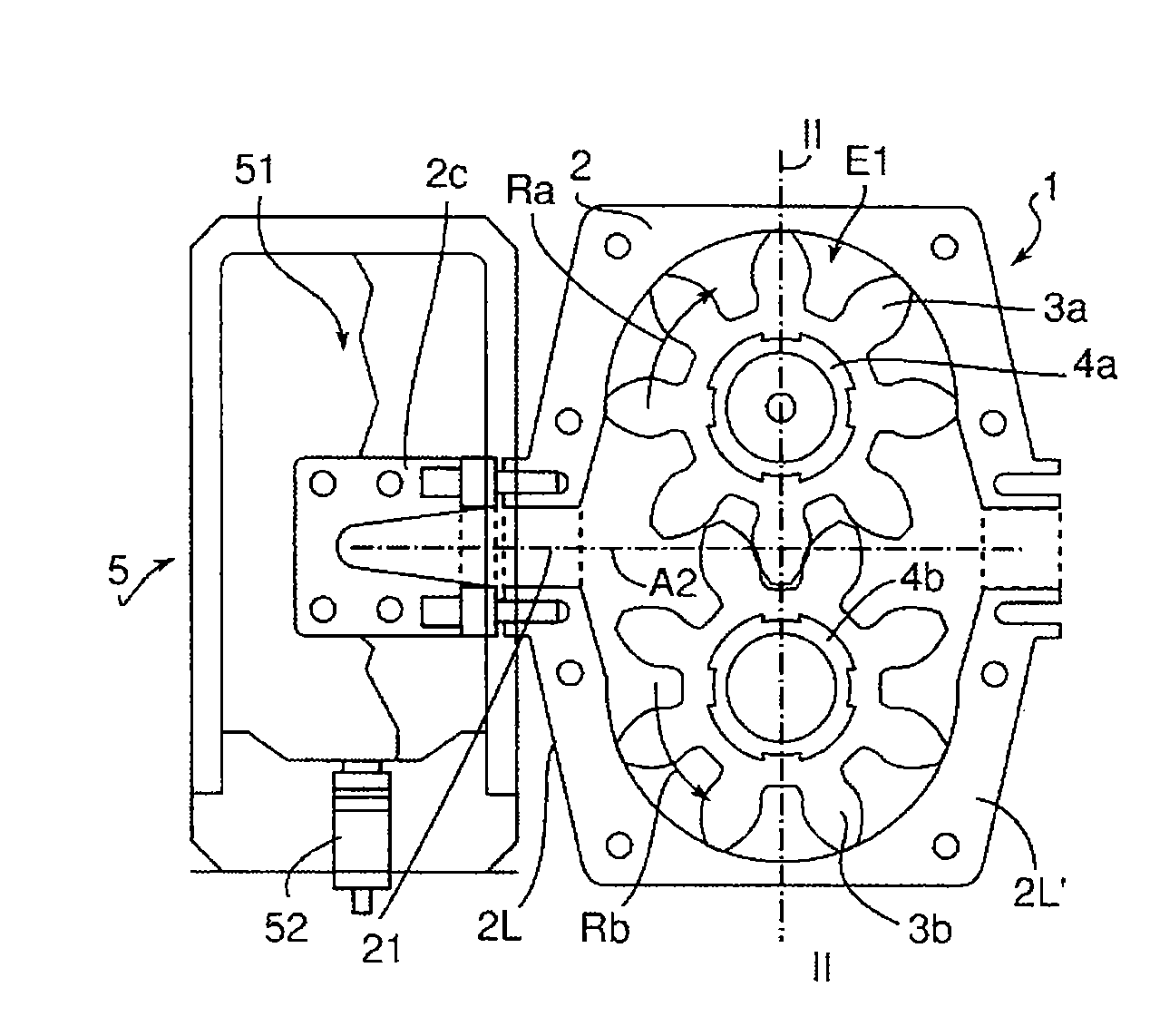

Image

  • Method and system for the emergency start-up of an energy generator set
  • Method and system for the emergency start-up of an energy generator set
  • Method and system for the emergency start-up of an energy generator set

Examples


Embodiment Construction

[0020]The invention seeks to provide emergency starters that allow responsiveness of this order of magnitude, namely within a few seconds, without having the disadvantages associated with the mass and size of the back-up hydraulic or pneumatic starters mentioned above.

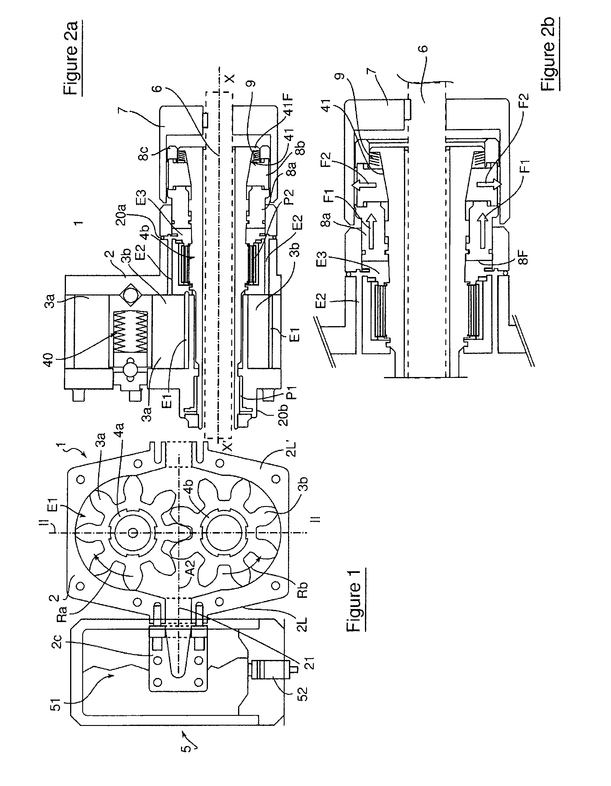
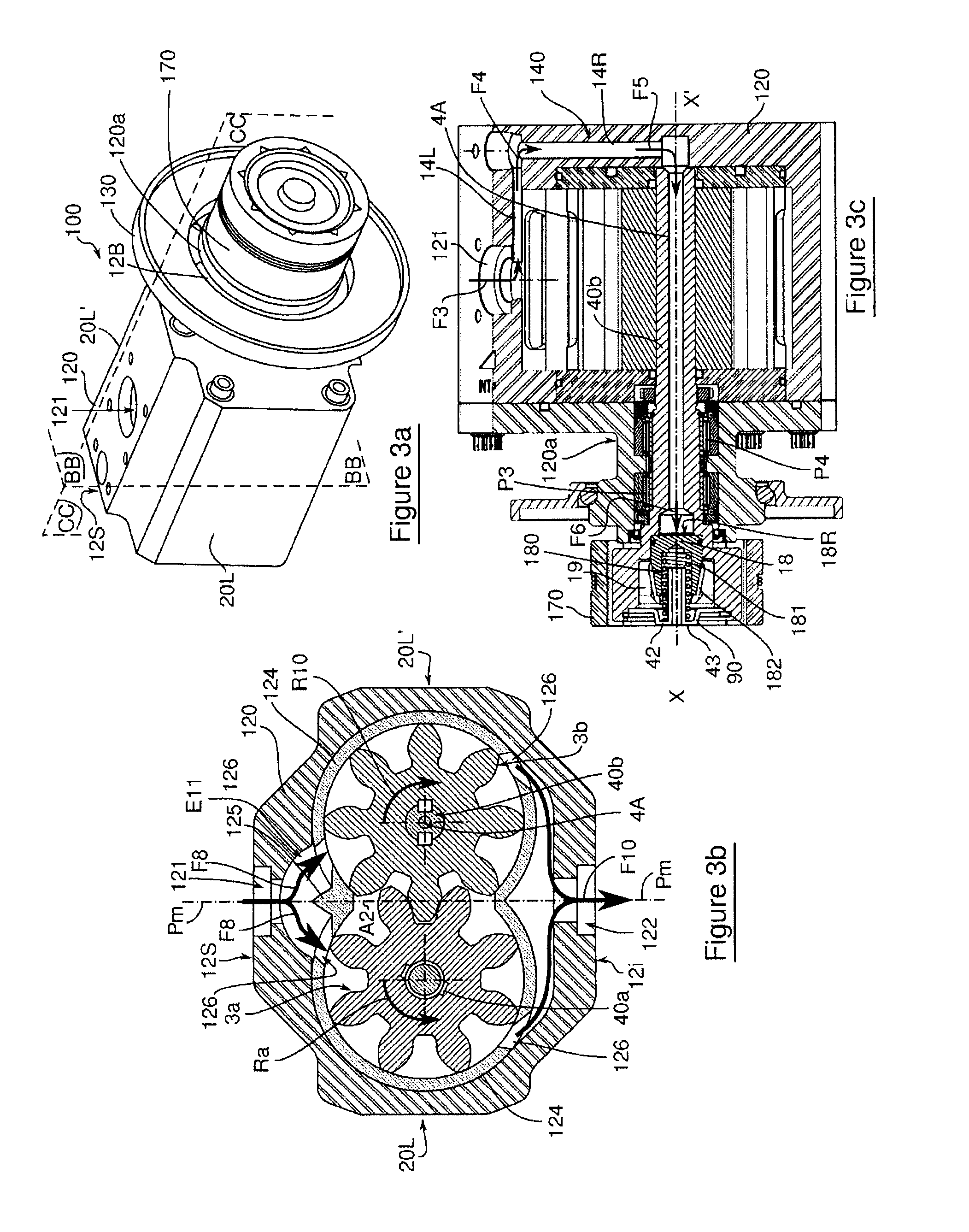
[0021]To achieve this, the present invention proposes coupling an instantaneous gas thrust of pyrotechnic type with a positive displacement transmission generator in conjunction with automatic coupling to / uncoupling from the set that is to be started.

[0022]More specifically, the object of the present invention is a method for emergency start-up of an energy generator set wherein, if an emergency start-up situation for the set is detected, at least one pyrotechnic gas combustion generator is triggered. Pressurised gases are then generated by this combustion and injected directly into a positive displacement motor with gear wheels, preferably straight-cut. A portion of these gases then rotates the gear wheels of the engi...


PUM


Abstract

An emergency starter that allows responsiveness within a few seconds, without having disadvantages associated with mass and size of a back-up hydraulic or pneumatic starter. An instantaneous gas thrust of pyrotechnic type is coupled with a positive displacement transmission generator in conjunction with automatic coupling to / uncoupling from a set that is to be started. An emergency start-up system includes at least one pyrotechnic gas generator connected to an electrical initiator itself connected to a computer, a positive displacement motor housing straight-cut gears, the pyrotechnic gas generator being coupled to the motor by an inlet in the casing. The motor includes a mechanism of connection capable of moving at one end of the drive shaft configured to couple the transmission shaft to a driven shaft of the set that is to be started via a centrifugal clutch.

Description

TECHNICAL FIELD[0001]The invention relates to a method and to a system for the emergency start-up of an energy generator set in critical situations where the dedicated traction system has stopped or is inadequate to meet requirements.[0002]The invention can be applied in the context of assistance or ultimate back-up to initiate the activation or reactivation of energy generation in various fields of technology:[0003]aeronautic traction systems for aeroplane or helicopter gas turbines;[0004]electrical engineering for ultra-limiting circuit breakers for the production and transmission of electrical power, particularly in submarines;[0005]in drilling or for marine immersion for master valve screws, robots etc; the field known as “Oil & Gas”;[0006]in extreme environments (hospitals, nuclear power stations, airports, server centres) for generators, pumps, safety valves etc.;[0007]in heat generation of a Stirling or Ericsson-type generator set;[0008]in hydraulic or pneumatic generation fo...

Claims


Application Information

Patent Timeline
Patent Type & Authority Applications(United States)
IPC IPC(8): F02C7/272F02C7/275
CPCF02C7/275F02C7/272Y02T50/60F02N13/00F02N15/10F02C7/26
Inventor FILIPUTTI, HUGUESGARDE, FRANCKTHIRIET, ROMAIN
Owner SAFRAN HELICOPTER ENGINES
Learn More