Separator Device

a technology of separator and separator tank, which is applied in the direction of sedimentation settling tank, space heating and ventilation details, domestic heating details, etc., can solve the problems of reducing the effectiveness of heating system, unwelcome constraint on installers, and water contamination by dir

Active Publication Date: 2015-05-14
ADEY HLDG
View PDF5 Cites 12 Cited by
  • Summary
  • Abstract
  • Description
  • Claims
  • Application Information

AI Technical Summary

Benefits of technology

[0011]Vertically in-line ports enable ease of fitting to a heating circuit. A section may be removed from the flow or return pipe of the heating circuit, and the open ends of the flow or return pipe connected to the first and second ports of the device via right-angle connectors. Since the first and second ports are on the same vertical line, no extra pipework will be required, and only one right-angle connector is needed on each of the inlet and outlet ports.
[0012]A circular flow of fluid enables effective separation of magnetic and nonmagnetic particles, by increasing the time for which a particular portion of fluid remains within the housing, without substantially affecting the fluid dynamics in the heating circuit, for example by reducing fluid pressure between inlet and outlet.
[0014]Providing deflectors on both of the ports allows either to be used as the inlet, providing the installer with additional flexibility when installing the device.
[0015]The deflector or deflectors may be angled from the vertical. The or each deflector may be angled to direct flow towards the end of the housing closest to the port adjacent to which the deflector is disposed. Angled deflectors deflect fluid not only into a swirl, but also towards separation chamber(s) disposed at end(s) of the housing. This increases the effectiveness of separation.

Problems solved by technology

Solid particles can also be present as contaminants in the water originally supplied to the system, and the water can become contaminated by dirt where an open expansion tank forms part of the system.
These solid particles can cause malfunction if they build up in the boiler or pump, and reduce the effectiveness of the heating system by restricting the flow of water and clogging radiators.
Due to the very tight space within which a device may need to be installed, particularly if it is being retrofitted to an existing installation, tangential inlet and outlet ports may impose an unwelcome constraint upon the installer.
In some cases it may simply not be possible to fit a device of suitable capacity with tangential or substantially tangential inlets.

Method used


Image

  • Separator Device
  • Separator Device
  • Separator Device

Examples


Embodiment Construction

)

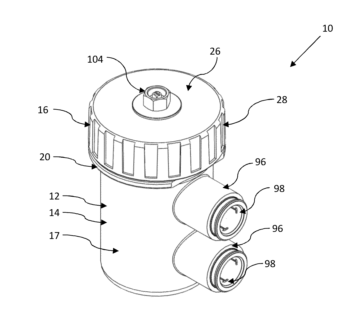
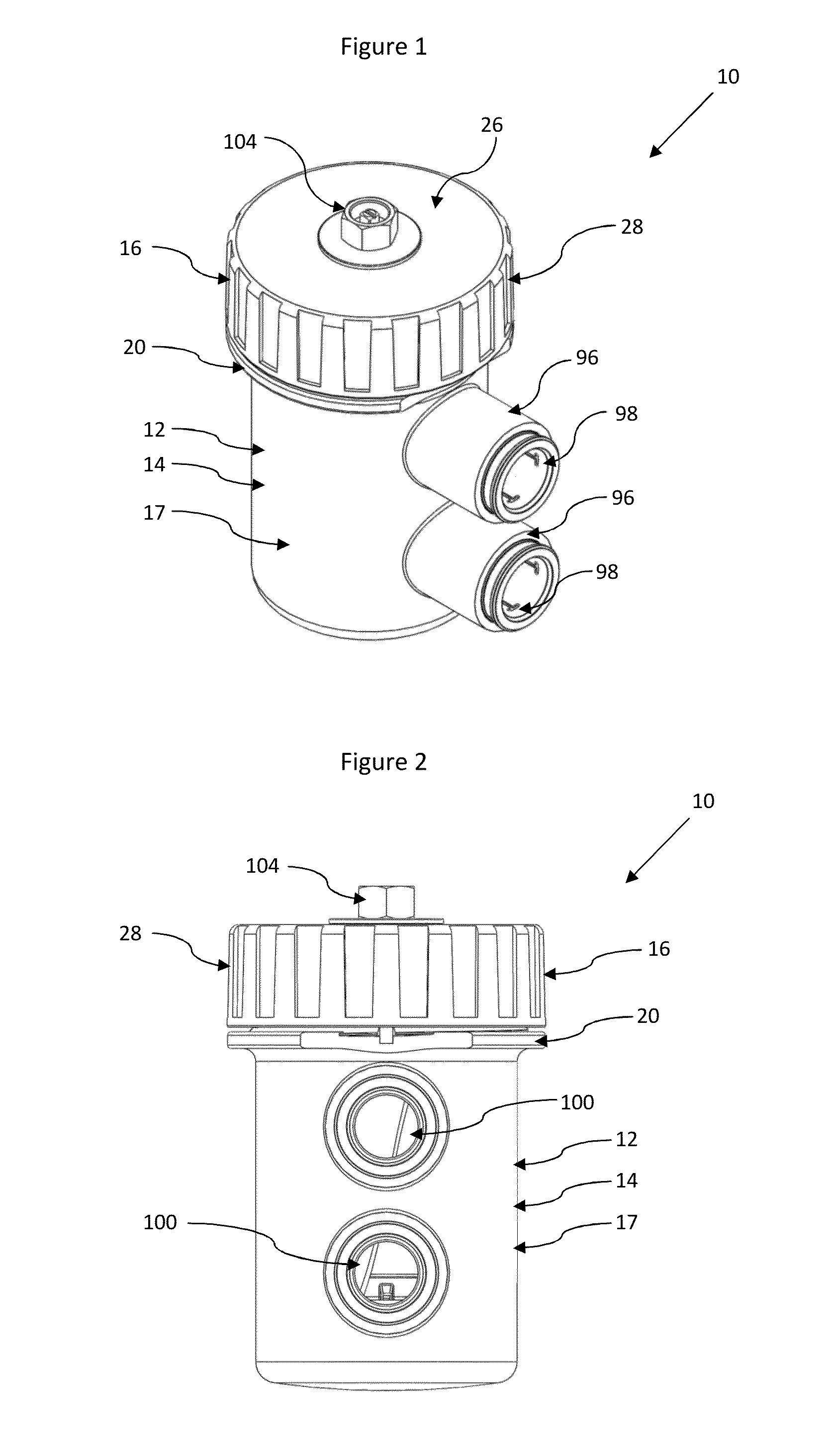
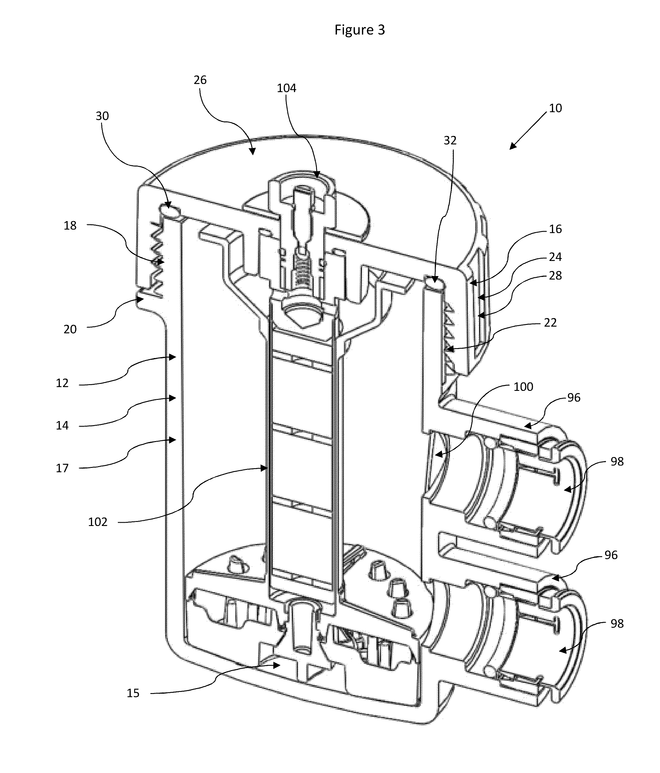
[0023]Referring to FIGS. 1 to 3, a separator device for separating particles from suspension in a fluid is indicated generally at 10. A housing 12 is provided, comprising of a body portion 14 and a removable closure portion 16. The body portion is substantially a cylindrical shell open at the upper end, that is, the body portion 14 comprises a floor 15 and a wall 17. The upper end of the wall 17 of the body portion 14 is formed with a male thread 18 and, directly below the male thread, a circumferential rim 20.

[0024]The closure portion 16 is in the form of a screw-on cap comprising a circular planar roof 26 and a circumferential wall 28 extending below the edge of the roof. A thread 22 is formed on the interior surface of the wall 28, for co-operating with the male thread 18 at the upper end of the wall 17 of the housing body portion 14. A plurality of recesses 24 are provided spaced uniformly around the outside of the wall 28 of the closure portion 16 in order to assist a user in ...


PUM

PropertyMeasurementUnit
angleaaaaaaaaaa
diameteraaaaaaaaaa
flow rateaaaaaaaaaa

Abstract

A separator device is provided for removing particles from suspension in a fluid comprises a housing having first and second ports for ingress and egress of fluid into and out of the housing, the first and second ports being on the same vertical line; and at least one separation chamber for separating solid particles from the fluid.

Description

[0001]The present invention relates to a separator device suitable for separating particles from a fluid flow and particularly but not exclusively to a separator device for use in a hydronic heating system.BACKGROUND TO THE INVENTION[0002]In a typical heating system, water is circulated by a pump through several radiators, possibly a heat exchanger in a hot water cylinder, and a boiler. During circulation, solid particles (for example, iron oxide) which have come loose from the interior of the radiators and pipework can become suspended in the water. Solid particles can also be present as contaminants in the water originally supplied to the system, and the water can become contaminated by dirt where an open expansion tank forms part of the system. These solid particles can cause malfunction if they build up in the boiler or pump, and reduce the effectiveness of the heating system by restricting the flow of water and clogging radiators. The water in a heating system should therefore ...

Claims


Application Information

Patent Timeline
Patent Type & Authority Applications(United States)
IPC IPC(8): B04C3/06
CPCB04C2003/003B04C3/06B01D21/0009B01D21/0042B01D21/2405B01D21/2483B01D21/267B03C1/286B03C2201/18F24D19/0092B01D21/00B01D21/0024B01D21/0087B01D21/24B01D21/2411B01D21/26B01D29/90B03C1/28B04C5/04F24D19/00Y02W30/50B01D21/265B01D21/262B01D35/06B01D46/0034B01D2247/02B01D2259/80B01D2259/814B03C1/00B03C1/30B04C5/06B04C5/08B04C5/185B04C5/187
Inventor ADEY, CHRISTOPHERDOWNIE, SIMON
Owner ADEY HLDG
Why Eureka
Try Eureka