Al technical title is built by PatSnap Al team. It summarizes the technical point description of the patent document.
a head and neck scanner and computed tomography technology, applied in tomography, instruments, applications, etc., can solve the problems of inability to work with cbct imaging in intensive care units (icu) or emergency rooms, risk and time loss, and difficulty in transporting
Active Publication Date: 2015-05-14
CARESTREAM HEALTH INC
View PDF57 Cites 17 Cited by
Summary
Abstract
Description
Claims
Application Information
AI Technical Summary
This helps you quickly interpret patents by identifying the three key elements:
Problems solved by technology
Method used
Benefits of technology
Problems solved by technology
However, workable systems have not been available for CBCT imaging in intensive care unit (ICU) or emergency room (ER) environments.
There may be an element of risk and time loss due to the need for transporting the patient.
Transport may b
Method used
Image
Click on the blue label to locate the original text in one second.
Reading with bidirectional positioning of images and text.
Examples
Embodiment Construction
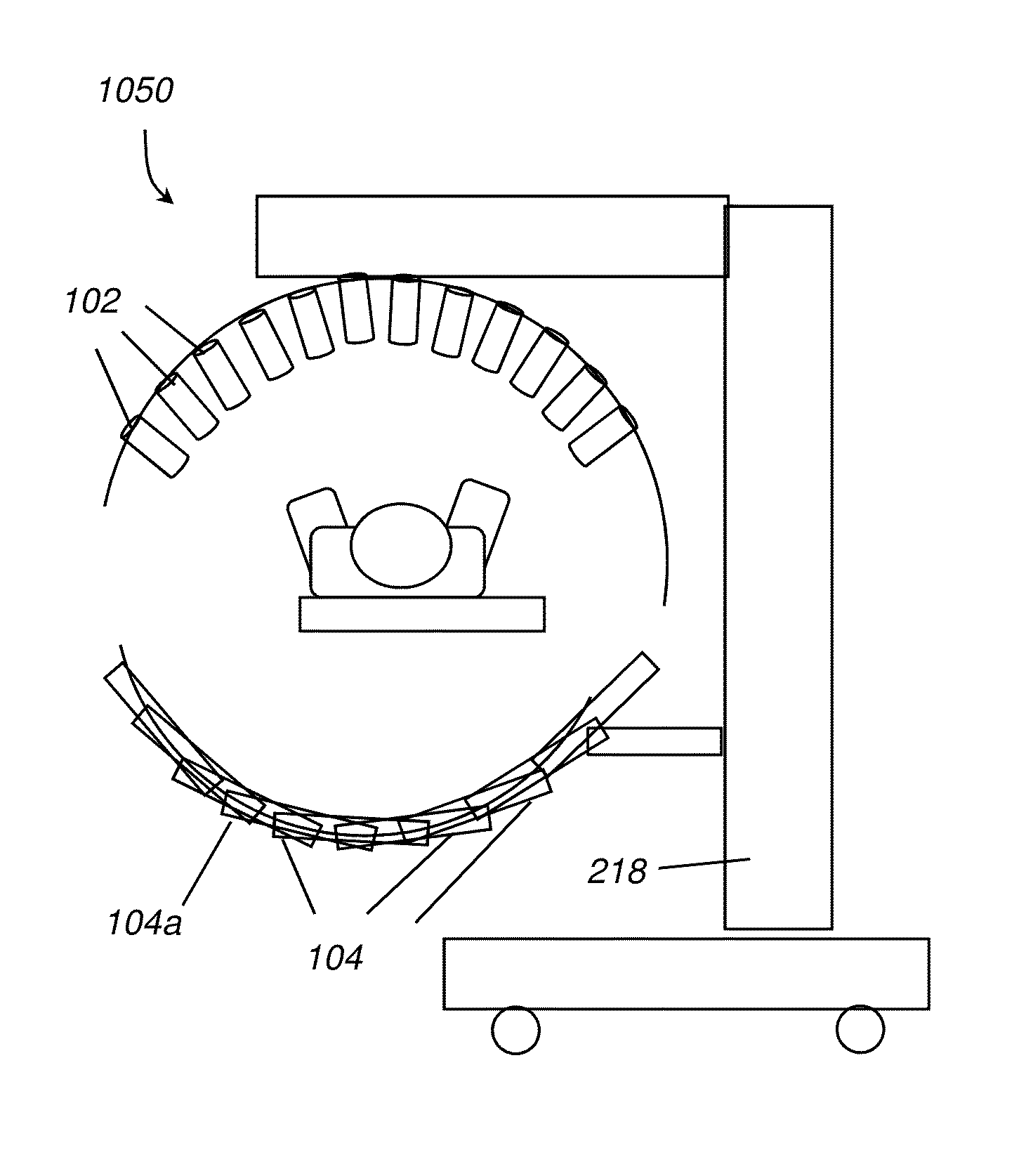
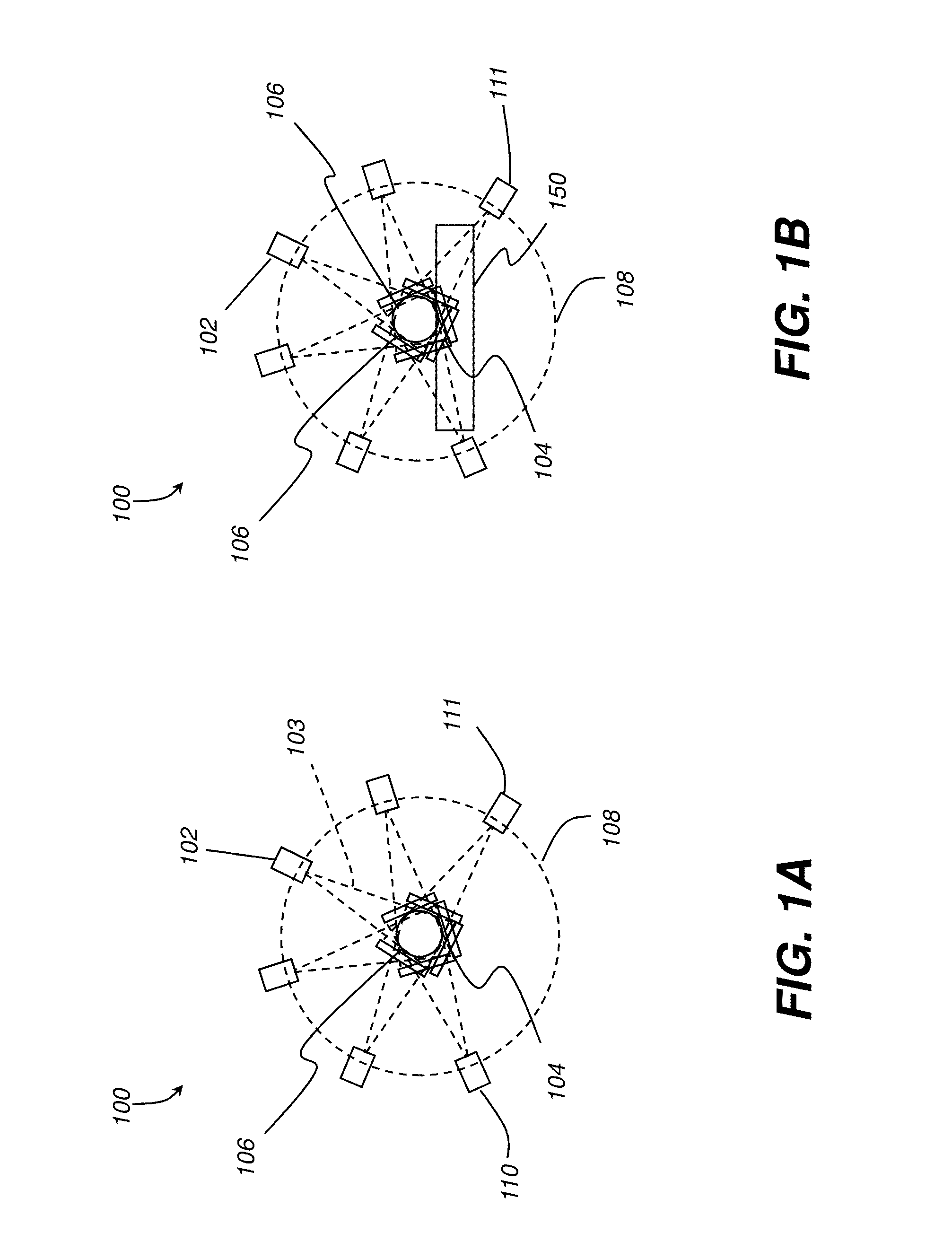
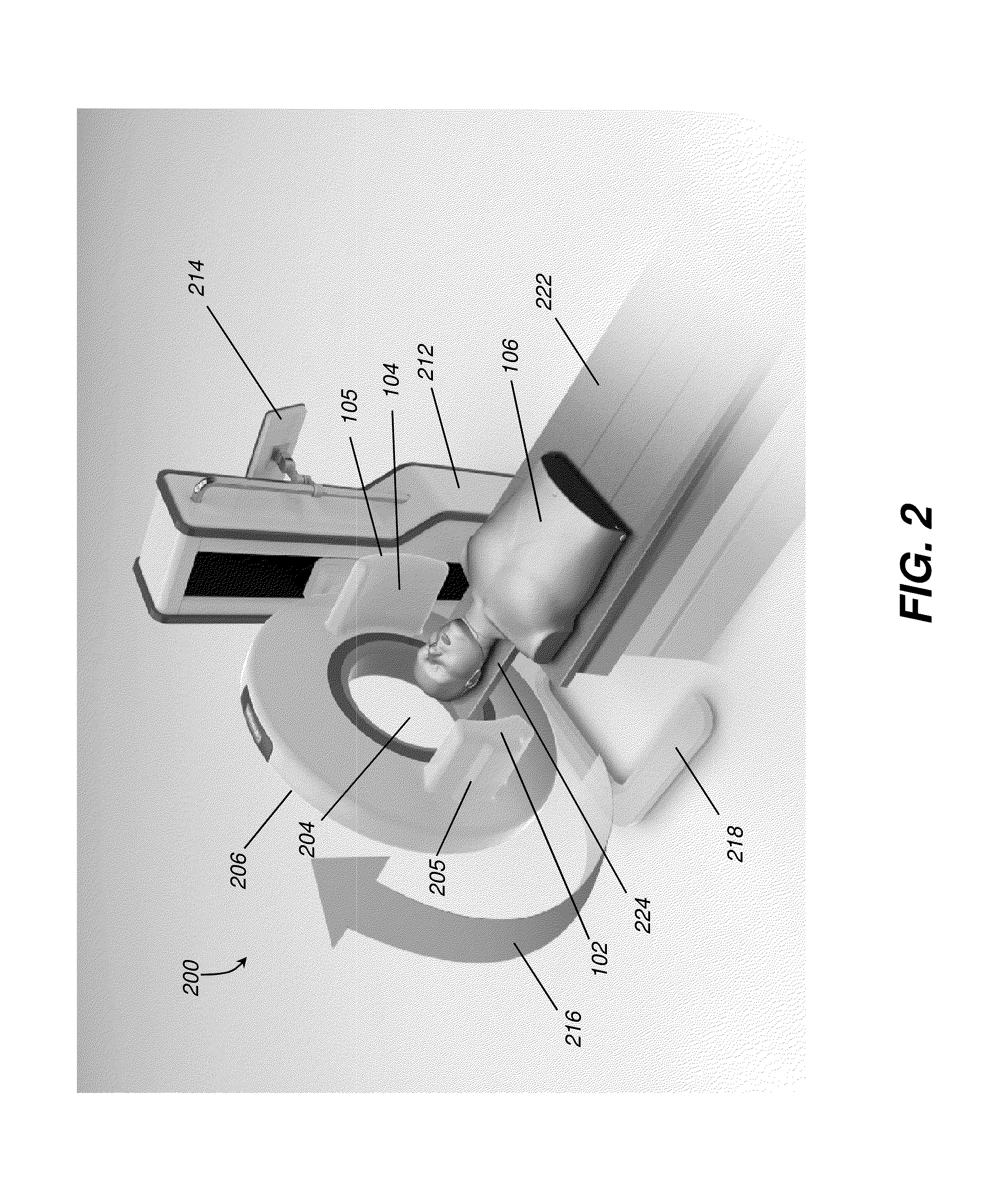
[0030]With reference to FIGS. 2, 3, and 4A-4C, a scanner gantry 206 mounts the radiation source 102 and DR detector 104 components for orbital movement about the head of the patient 106 in a direction indicated by the arrow 216 to achieve 180 degrees plus cone angle coverage of the head and neck. The gantry 206 may be arranged in a number of ways. In one embodiment, shown schematically in FIGS. 2, 3, and 4A-4C, the source 102 and detector 104 orbit the subject 106 within the outer circumference of the gantry 206. The gantry 206 may be vertically moved to adjust for the height of the bed or other platform 222 on which the patient lies. The column 212 supports the gantry 206 and may include a motorized mechanism to move the gantry 206 vertically 402, 404, as shown in FIG. 4B, as well as to tilt the gantry. The support column 212 may also be attached to a base portion 218. The base portion 218 may also be fitted with wheels 302 for easing movement of the imaging system 200 across a flo...
PUM
Abstract
An imaging system comprises a digital radiation detector and radiation source. A detector transport moves the detector along at least a portion of a first curved path and a radiation moves the source along at least a portion of a second curved source path. The detector is configured to travel at least a portion of the first curved path, and the source is configured to travel at least a portion of the second curved path. The detector is configured to obtain a plurality of 2D projection images over a range of scan angles for reconstructing a 3D volume image using the plurality 2D projection images.
Description
CROSS REFERENCE TO RELATED APPLICATIONS[0001]This application claims priority to U.S. Patent Application Ser. No. 61 / 902,819, filed Nov. 12, 2013, in the name of Yorkston et al., and entitled EXTREMITY IMAGING SCANNER FOR THE HEAD AND NECK.[0002]This application is related in certain respects to U.S. Pat. No. 8,210,745, issued Jul. 3, 2012, in the name of Yorkston et al., and entitled EXTREMITY IMAGING APPARATUS FOR CONE BEAM COMPUTED TOMOGRAPHY; U.S. Pat. No. 8,348,506, issued Jan. 8, 2013, in the name of Yorkston et al., and entitled EXTREMITY IMAGING APPARATUS FOR CONE BEAM COMPUTED TOMOGRAPHY; U.S. Pat. No. 8,672,543, issued Mar. 18, 2014, in the name of Kralles et al., and entitled COUNTERWEIGHT FOR MOBILE X-RAY DEVICE; and U.S. Pat. No. 8,876,379, issued Nov. 4, 2014, in the name of DiRisio et al., and entitled COLLAPSIBLE COLUMN MOVEMENT APPARATUS FOR MOBILE X-RAY DEVICE; all of which are incorporated herein by reference in their entirety.BACKGROUND OF THE INVENTION[0003]The ...
Claims
Application Information
Patent Timeline
Application Date:The date an application was filed.
Publication Date:The date a patent or application was officially published.
First Publication Date:The earliest publication date of a patent with the same application number.
Issue Date:Publication date of the patent grant document.
PCT Entry Date:The Entry date of PCT National Phase.
Estimated Expiry Date:The statutory expiry date of a patent right according to the Patent Law, and it is the longest term of protection that the patent right can achieve without the termination of the patent right due to other reasons(Term extension factor has been taken into account ).
Invalid Date:Actual expiry date is based on effective date or publication date of legal transaction data of invalid patent.