
Surface-mount type electric connecting terminal, and electronic module unit and circuit board using the same

Active Publication Date: 2015-05-14
JOINSET +1
View PDF3 Cites 16 Cited by
  • Summary
  • Abstract
  • Description
  • Claims
  • Application Information

AI Technical Summary

Benefits of technology

The present invention provides a surface-mount type electric connecting terminal that is shorter in height and has a longer operating distance. Additionally, it improves soldering strength during the reflow soldering process, which is conducted in a vacuum pickup process.

Problems solved by technology

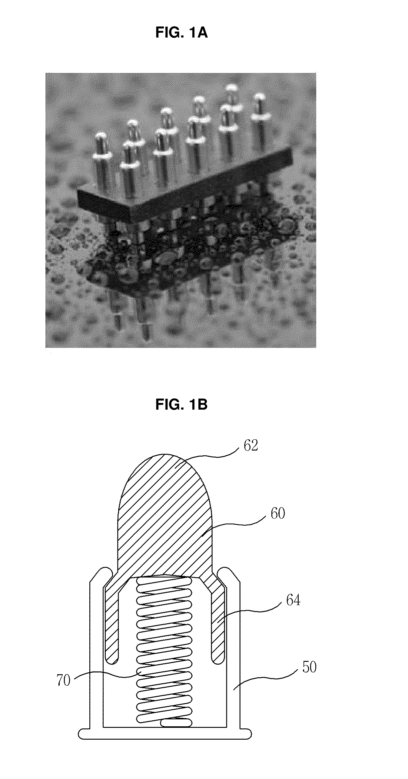
However, since it does not need to fix such a metallic spring to a metallic sheet such that the metallic spring is temporarily fixed so as to keep the metallic spring before a reflow process or such that the metallic spring is maintained in a simple inserted state, a vacuum pickup process may be hard for the sake of surface-mounting work.
Since there is not any assistant portion to hold the spring in place within the top and bottom cylinders, the inner spring may be distorted during compression.
In this reason, it is hard to economically manufacture the products whose heights are about 2 mm or more and operating distances are longer.
The above-described problems occur because it was not considered to independently solder the pogo pin onto the printed circuit board at initial stages.
For this reason, it is hard to provide a pogo pin which has a low height and a long operating distance in up and down directions, and it is hard to mount the pogo pin onto a printed circuit board using a reel tape through a reflow soldering process using vacuum pickup and solder cream.
Since the plunger 60 of the pogo pin is manufactured by cutting a typical metal, manufacturing costs is a lot, and there is a limit in making the plunger 60 thinner.

Method used


Image

  • Surface-mount type electric connecting terminal, and electronic module unit and circuit board using the same
  • Surface-mount type electric connecting terminal, and electronic module unit and circuit board using the same
  • Surface-mount type electric connecting terminal, and electronic module unit and circuit board using the same

Examples


Embodiment Construction

[0081]Now, the surface-mount type electric connecting terminal according to the exemplary embodiments of the present invention will be described in detail with reference to the accompanying drawings.

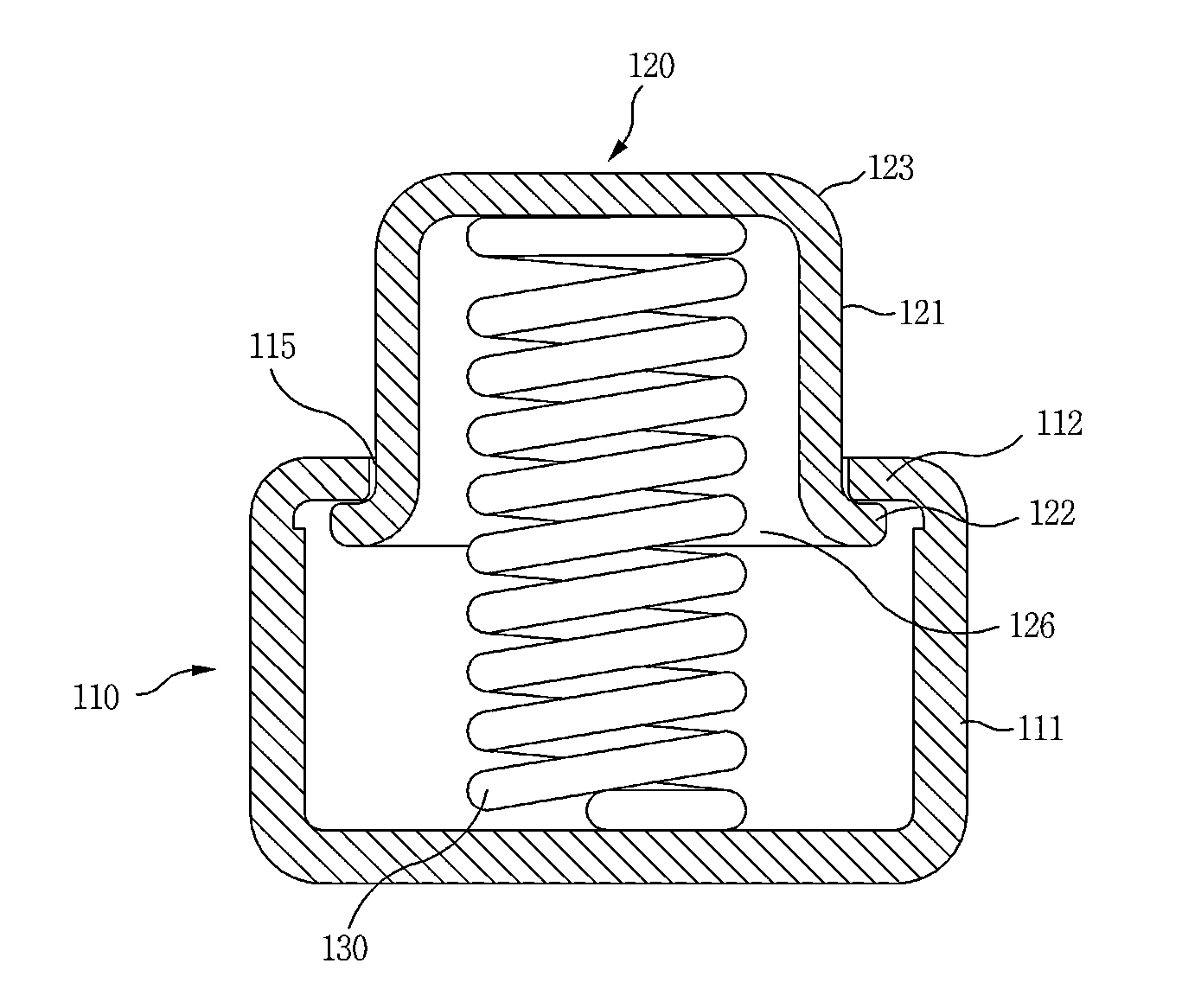
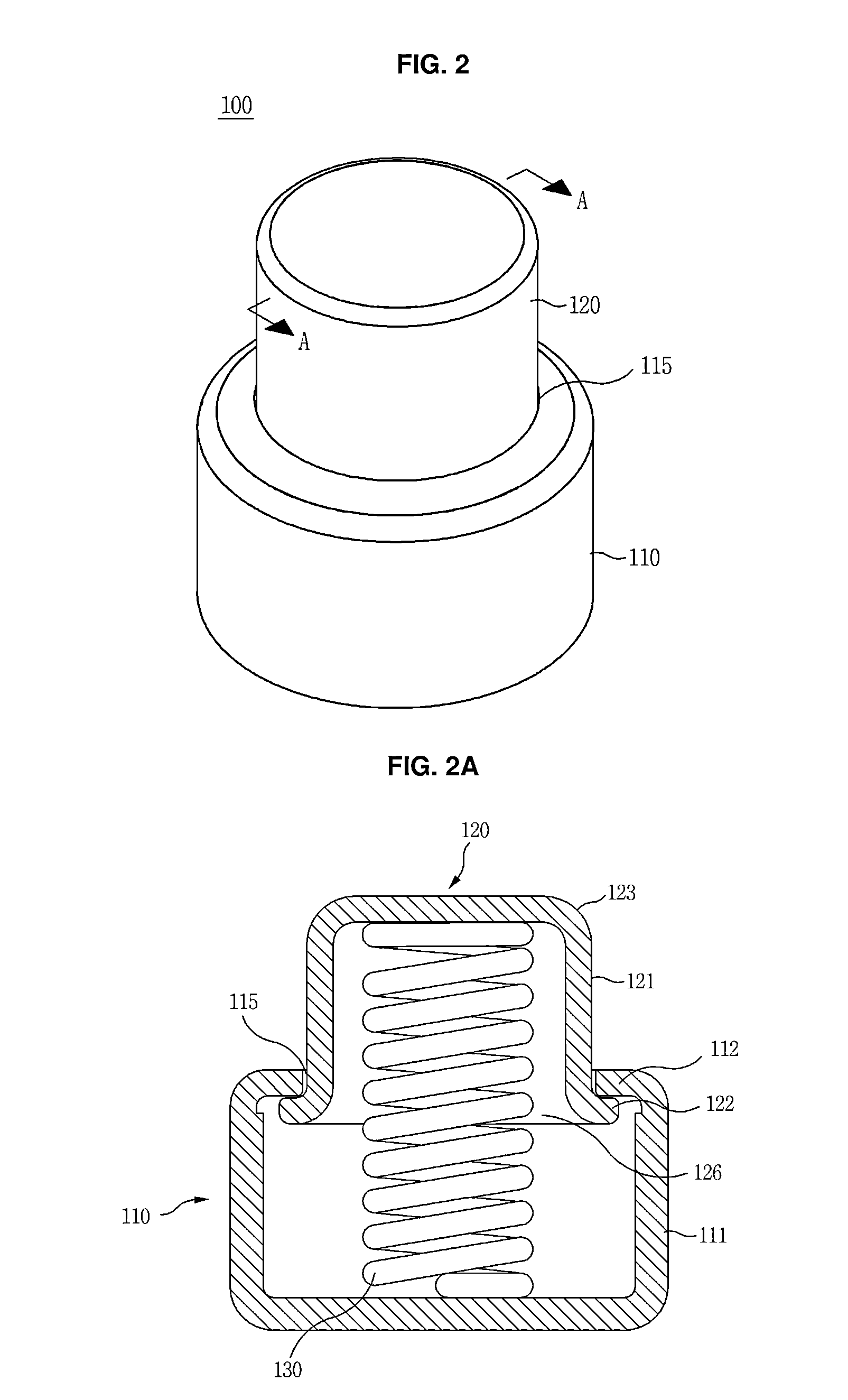
[0082]FIG. 2 is a perspective view illustrating a surface-mount type electric connecting terminal according to an exemplary embodiment of the present invention, FIG. 2A is a cross sectional view taken along line A-A in FIG. 2, FIGS. 3A and 3B are views illustrating a state before and after a movable member is pressed, and FIGS. 4A and 4B are photos illustrating actual products of a surface-mount type electric connecting terminal. Referring to FIGS. 2 and 2A, a surface-mount type electric connecting terminal 100 includes a fixed member 110 which is made from a metallic material, a movable member 120 which may slide against the fixed member 110 and is made from a metallic material, and a spring 130 which provides elastic force and elastic recovery force by which the movable member 120 may ...


PUM


Abstract

Provided is a surface-mount type electric connecting terminal which is disposed between opposing conductive objects and is configured to electrically connecting the objects while easily adjusting pressing force and recovery force. The electric connecting terminal includes a cylindrical fixed member which is made from a metallic material; a cylindrical movable member which is slidably inserted in the fixed member and is made from a metallic material; and an electrical conductive spring which is accommodated in the fixed member and whose one end contacts with the bottom of the fixed member and the other end contacts with the bottom of the movable member for thereby allowing the movable member to elastically slide against the fixed member.

Description

REFERENCE TO RELATED APPLICATIONS[0001]This application claims the priority benefit of Korean Patent Application No. 10-2013-0138676 filed on Nov. 14, 2013, Korean Patent Application No. 10-2014-0043738 filed on Apr. 11, 2014, and Korean Patent Application No. 10-2014-0046947 filed on Apr. 18, 2014, the entire contents of which are incorporated herein by reference.FIELD OF THE INVENTION[0002]The present invention relates to a surface-mount type electric connecting terminal, and more particularly, to a surface-mount type electric connecting terminal which is disposed between opposing conductive objects to electrically connect the objects to each other with high reliability and easily adjusts pressing force and recovering force.[0003]Furthermore, the present invention relates to a surface-mount type electric connecting terminal which makes it possible to minimize the delaminating and leaning during soldering, obtain a longer operating distance as compared with the height of a product,...

Claims


Application Information

Patent Timeline
IPC IPC(8): H01R13/24
CPCH01R13/2464H01R13/2428H01R13/2421H01R4/028H01R12/57H01R12/718H01R2201/02H05K3/341H05K2201/1031Y02P70/50
Inventor KIM, SUN-KIKANG, TAE-MAN
Owner JOINSET
Learn More