Hinged transcranial magnetic stimulation array for novel coil alignment

a transcranial magnetic stimulation and coil technology, applied in the field of transcranial magnetic stimulation (tms) methods, can solve the problems of raising safety concerns, fixed coil tms electromagnets currently available are not configured to produce an elongated path of induced electrical curren

Inactive Publication Date: 2015-05-14
RIO GRANDE NEUROSCI
View PDF4 Cites 37 Cited by
  • Summary
  • Abstract
  • Description
  • Claims
  • Application Information

AI Technical Summary

Benefits of technology

[0016]TMS electromagnets may be held to the adjustable head frame by one or more holders that retain the TMS electromagnet(s) on the head frame, but allows it to be adjusted so that the shape of the TMS electromagnets may be conformed to the subject's head. The holder(s) may be configured so that they generally aim the TMS electromagnets to a predetermined target, but allow just enough movement of the TMS electromagnets so that they can conform to the head.
[0017]Thus also generally described herein are adjustable Transcranial Magnetic Stimulation (TMS) electromagnets (adjustable TMS electromagnet devices), that may include: a first TMS coil comprising multiple coil windings; a second TMS coil comprising multiple coil windings; an adjustable connecting region between the first TMS coil and the second TMS coil, wherein the adjustable connecting region is configured so that the angle between the first and second TMS coils may be adjusted; and a lock configured to hold the adjustable connecting region in a predetermined position, wherein the first TMS coil and the second TMS coil are electrically connected through the adjustable connecting region so that current flows between the first TMS coil and the second TMS coil. Although TMS electromagnets having two coils are described and shown herein, it should be understood that these devices may include three, four, or more coils; these coils may be connected at a single connecting region or multiple adjustable connecting regions may be included.

Problems solved by technology

However, the fixed-coil TMS electromagnets currently available are not configured to produce an elongated path of induced electrical current along a pre-defined trajectory while adapting to differences in the curvature of each patient's head.
For example, even the more physically flexible, large-coil designs currently available stimulate too much brain tissue lateral to the targeted strip, and thereby raise safety concerns.

Method used


Image

  • Hinged transcranial magnetic stimulation array for novel coil alignment
  • Hinged transcranial magnetic stimulation array for novel coil alignment
  • Hinged transcranial magnetic stimulation array for novel coil alignment

Examples


Embodiment Construction

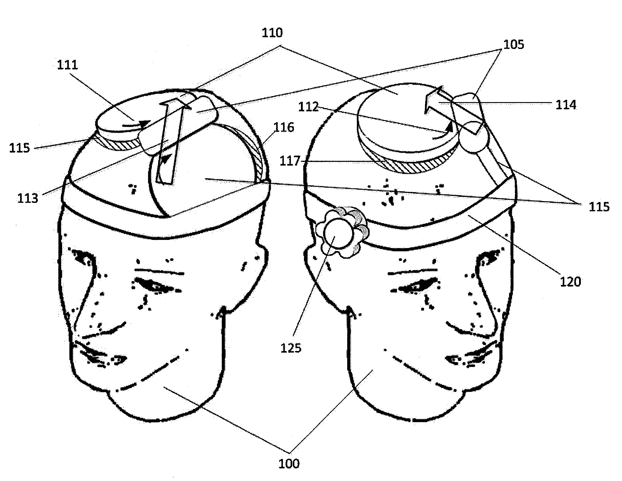
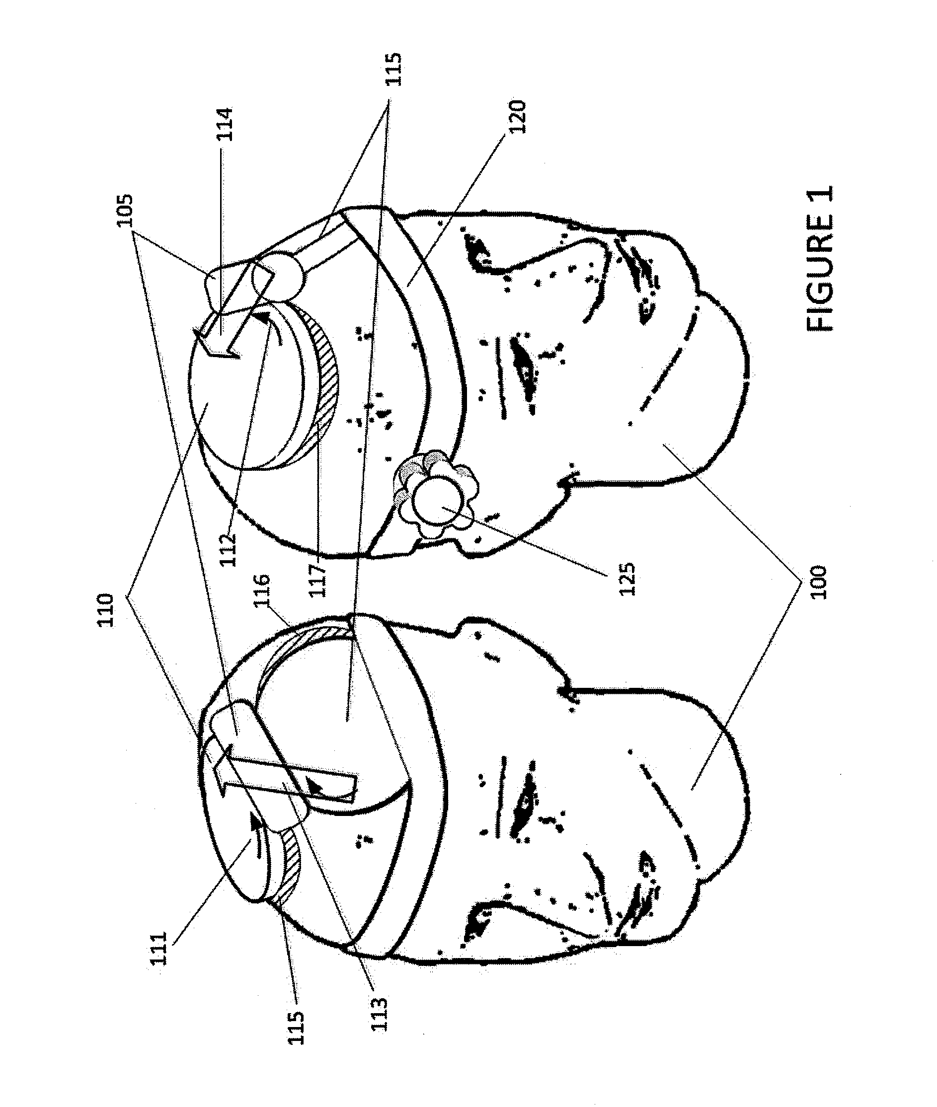
[0036]In general, the devices described herein include one or more TMS electromagnets that are configured to be worn on a patients head to induce current in a specific target region of the patient's brain (e.g., the left dorsolateral prefrontal cortex overlaying the dorsal anterior cingulate gyrus). The devices maybe configured to stimulate this region specifically (and without substantially stimulating non-target regions) in a variety of head sizes and shapes using the same device.

[0037]In some variations this device includes a head mount holding the TMS electromagnet, which may be configured as a hat, helmet, headband, or the like. The position or orientation of the TMS electromagnets (which may include two or more TMS electromagnets or coils) may be fixed, while various subcomponents of the TMS electromagnets may be adjustable.

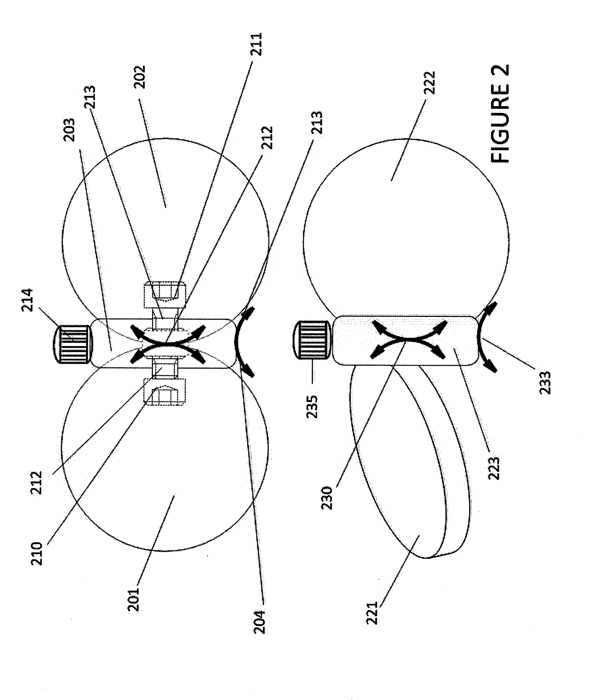
[0038]For example, FIG. 1 illustrates a set of two coils with a hinge apparatus retaining the two in proximity, and with underlying hemi-pads keeping the c...


PUM


Abstract

Adjustable devices and methods of adjusting and customizing Transcranial Magnetic Stimulation (TMS) electromagnets to produce an elongated path of induced electrical current along a user-defined trajectory in patients having a variety of different head shapes and curvatures. Existing TMS electromagnets (“coils”) allow only limited adjustment of the current delivery surfaces. The present invention provides means for adjusting the sub-coil loops within a double coil structure. The present design may be powered with the use of a single TMS pulse generator unit.

Description

CROSS REFERENCE TO RELATED APPLICATIONS[0001]This patent application claims priority to provisional patent application No. 61 / 642,290, filed on May 3, 2012. This provisional patent application is herein incorporated by reference in its entirety.INCORPORATION BY REFERENCE[0002]All publications and patent applications mentioned in this specification are herein incorporated by reference in their entirety to the same extent as if each individual publication or patent application was specifically and individually indicated to be incorporated by reference.FIELD OF THE INVENTION[0003]Described herein are Transcranial Magnetic Stimulation (TMS) methods, devices and systems. In particular, TMS coils that are adjustable to a patient's head are described. Systems may include TMS electromagnets with a pair of coils that are adjustable so that the angle between the coils can be changed and held in selected positions.BACKGROUND OF THE INVENTION[0004]Typical transcranial magnetic stimulation (TMS)...

Claims


Application Information

Patent Timeline
Patent Type & Authority Applications(United States)
IPC IPC(8): A61N2/02A61N2/00
CPCA61N2/006A61N2/02
Inventor SCHNEIDER, M. BRETSADLER, JOHN W.BECKY, BRIANYANG, AI-TING STEPHANIE
Owner RIO GRANDE NEUROSCI
Why Eureka
Try Eureka