
Shoe Sole Having Diagonal Groove

a technology of diagonal grooves and soles, applied in the field of shoe soles having diagonal grooves, can solve the problems of insufficient realization of functions, and achieve the effect of reducing the weight of the midsole and reducing the weight of the sol

Inactive Publication Date: 2015-05-21
ASICS CORP
View PDF7 Cites 54 Cited by
  • Summary
  • Abstract
  • Description
  • Claims
  • Application Information

AI Technical Summary

Benefits of technology

The patent describes a shoe design that reduces the eversion of the heel area. To achieve this, the shoe needs to have a rigid torsional structure that reduces the rotation of the foot around the subtalar joint. The shoe also has a U-shaped outsole that reduces the weight of the shoe by cutting out the central section of the rear foot. Additionally, a diagonal groove is formed in the midsole to further reduce weight while still maintaining torsional rigidity. These features make the shoe lighter and more comfortable to wear while still providing the necessary support and stability.

Problems solved by technology

However, these functions cannot be realized sufficiently only by forming a diagonal groove in a shoe sole.

Method used


Image

  • Shoe Sole Having Diagonal Groove
  • Shoe Sole Having Diagonal Groove
  • Shoe Sole Having Diagonal Groove

Examples


embodiment

[0084]The present invention will be understood more clearly from the following description of preferred embodiments taken in conjunction with the accompanying drawings. Note however that the embodiments and the drawings are merely illustrative, and should not be relied upon in defining the scope of the present invention. The scope of the present invention shall be defined only by the appended claims. In the accompanying drawings, like reference numerals denote like components throughout the plurality of figures.

[0085]One embodiment of the present invention will now be described with reference to the drawings.

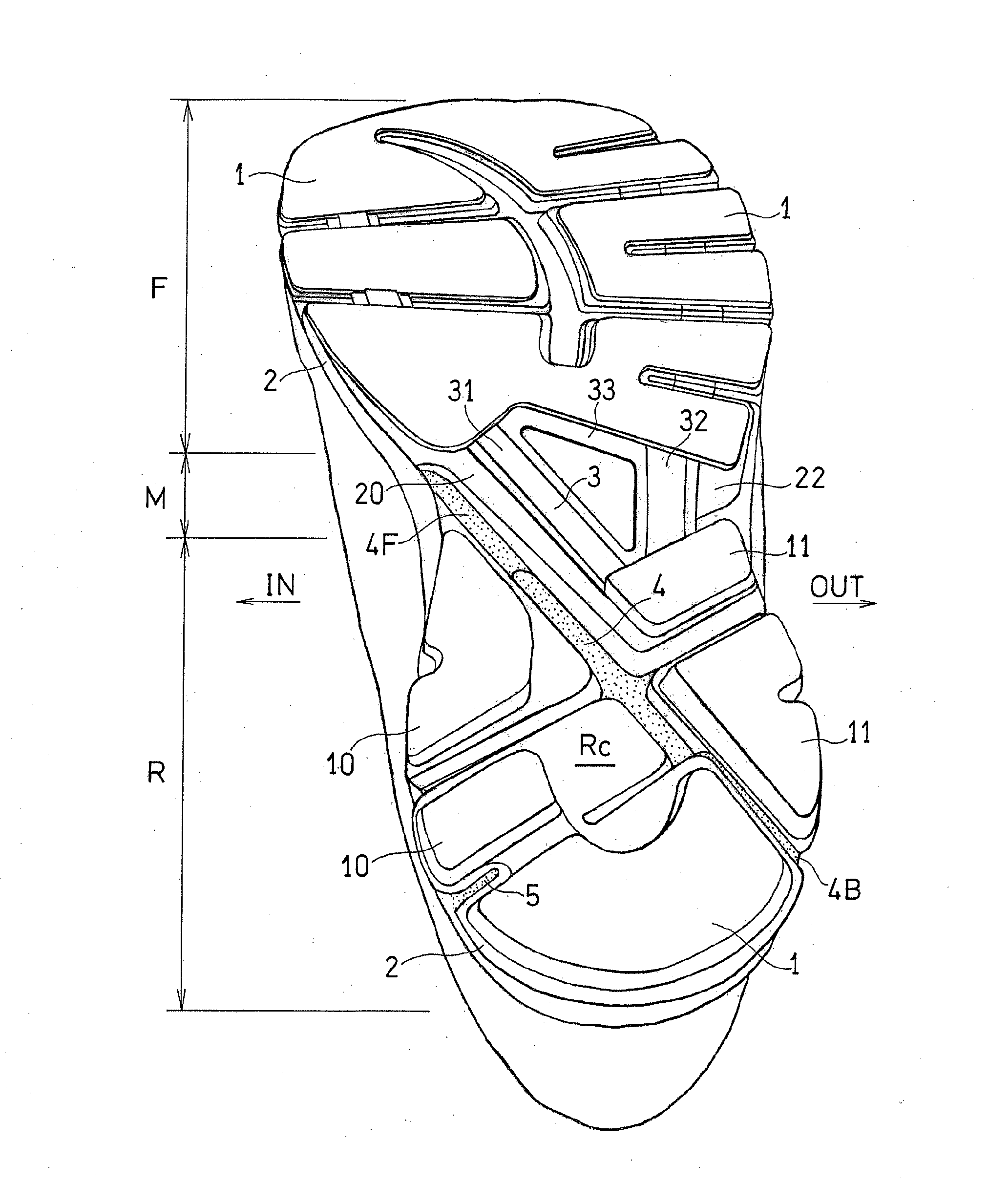
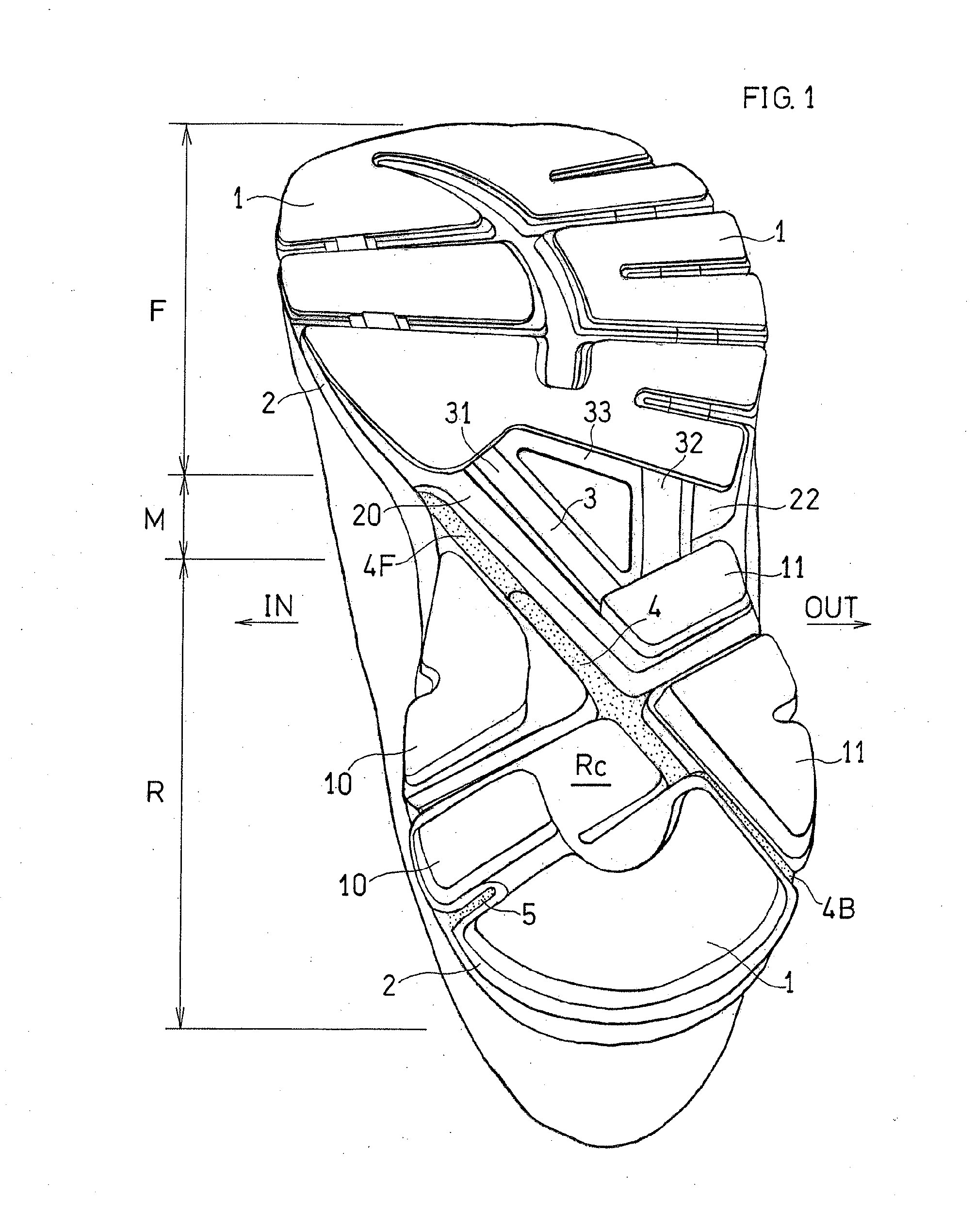
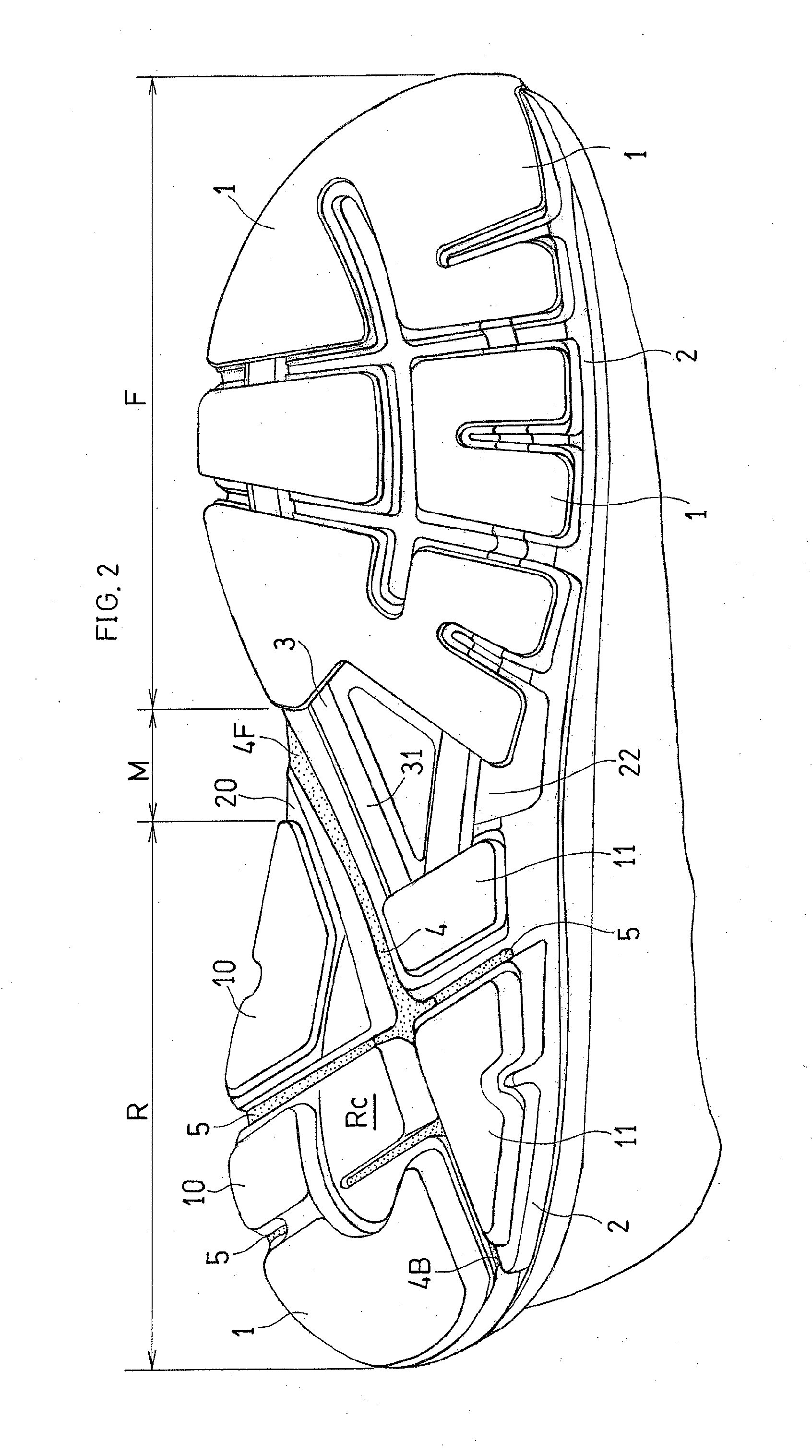
[0086]As shown in FIGS. 1 and 2, the shoe sole includes the outsole 1 and the midsole 2. Note that FIGS. 1 to 5 do not show small grooves (so called “design”) formed in the tread surface of the outsole 1.

[0087]As indicated by the regular dots in FIG. 3, the outsole 1 is arranged over the front foot section F and the rear foot section R. The outsole 1 is formed by a foamed body o...


PUM


Abstract

A shoe sole including: an outsole having a tread surface to be in contact with a road surface; and a midsole arranged on the outsole, wherein: the midsole is exposed in a central section of a rear foot section and an arch section; in the central section and a lateral side section of the rear foot section of the shoe sole, a diagonal groove is formed extending in a diagonal front-rear direction in the rear foot section to an outer edge of a lateral side of the rear foot section; an angle β, formed between a virtual center line of the diagonal groove and a longitudinal axis connecting between a center of a heel and a middle point between a big-toe ball and a little-toe ball, is set in a range of 12° to 35°; and a virtual intersection point between the longitudinal axis and the center line is set within a range of 21% to 43% of a full length of the longitudinal axis of the shoe sole from a posterior end of the shoe sole, the diagonal groove extending to a point anterior and medial to the intersection point.

Description

TECHNICAL FIELD[0001]The present invention relates to a shoe sole having a diagonal groove.BACKGROUND ART[0002]Shoe soles having a diagonal groove are known in the art. (the first patent document)CITATION LISTPatent Literature[0003]First Patent Document: JP 2008-620 A (FIG. 4, FIG. 10(b))[0004]Second Patent Document: JP H07-236503 ASUMMARY OF INVENTION[0005]As is well known in the art, a shoe sole is required to be light in weight, be capable of suppressing eversion of the heel area, and serve to absorb the impact on the heel area.[0006]However, these functions cannot be realized sufficiently only by forming a diagonal groove in a shoe sole.[0007]It is therefore an object of the present invention to form an appropriate diagonal groove so as to realize these functions.[0008]The present invention in one aspect is a shoe sole including:[0009]an outsole 1 having a tread surface to be in contact with a road surface; and a midsole 2 arranged on the outsole 1, wherein:[0010]in a central se...

Claims


Application Information

Patent Timeline
Patent Type & Authority Applications(United States)
IPC IPC(8): A43B13/22
CPCA43B13/223A43B13/14A43B13/141
Inventor INOMATA, TAKASHINISHIWAKI, TSUYOSHIFUJIWARA, MASAHIROANDO, YOSHIYASU
Owner ASICS CORP
Learn More