High efficiency ventilation system

a ventilation system and high efficiency technology, applied in the field of high efficiency ventilation system, can solve the problems of increasing temperature and humidity, requiring additional energy to reduce temperature, etc., and achieve the effect of high efficiency, convenient transfer of refrigerant, and high efficiency

Active Publication Date: 2015-05-21
LEADER INVESTMENTS LLC
View PDF10 Cites 11 Cited by
  • Summary
  • Abstract
  • Description
  • Claims
  • Application Information

AI Technical Summary

Benefits of technology

[0005]A high efficiency ventilation system is presented. In one or more embodiments, a high efficiency ventilation system may comprise a partition configured to separate a supply air stream and a return air stream, an energy recovery ventilator, a heat recovery ventilator, a refrigerant flow controlling condensing unit, and a direct expansion coil. Illustratively, the refrigerant flow controlling condensing unit may be directly or indirectly connected to the direct expansion coil. In one or more embodiments, the refrigerant flow controlling condensing unit may be configured to facilitate a transfer of a refrigerant from the refrigerant flow controlling condensing unit to the

Problems solved by technology

Thus, continuously supplying outside air to the controlled environment may increase a temperature and a humidity of the controlled environment and additiona

Method used


Image

  • High efficiency ventilation system
  • High efficiency ventilation system
  • High efficiency ventilation system

Examples


Embodiment Construction

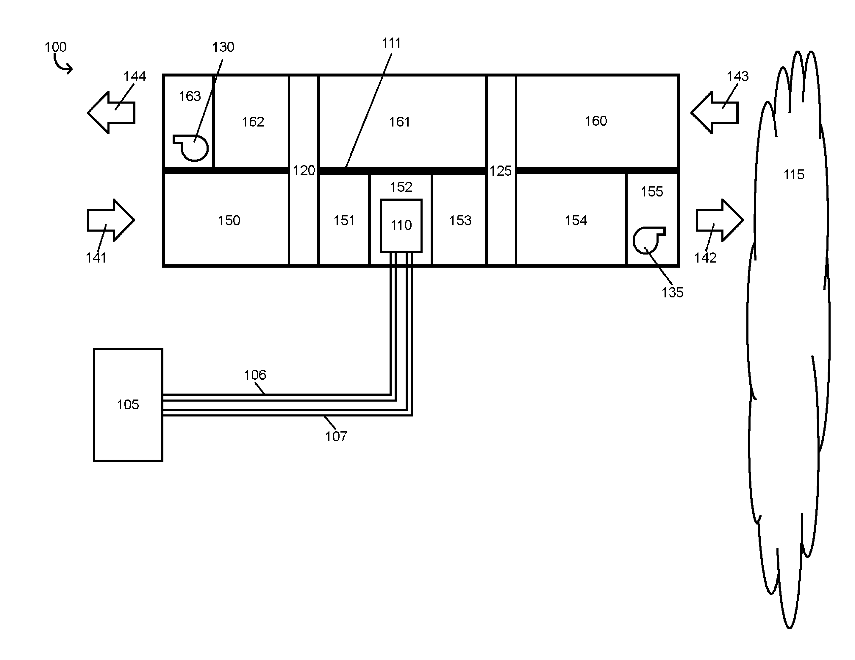
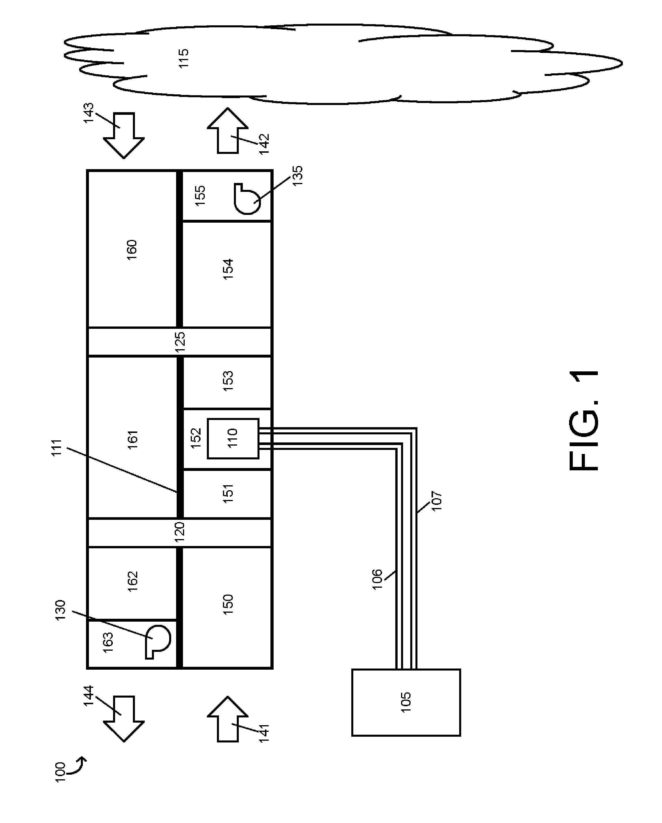
[0013]FIG. 1 is a schematic diagram illustrating a high efficiency ventilation system in a heat pump configuration 100. Illustratively, high efficiency ventilation system in a heat pump configuration 100 may be configured to ventilate a controlled environment 115 in accordance with American Society of Heating, Refrigerating and Air-Conditioning Engineers required minimum ventilation rates. In one or more embodiments, high efficiency ventilation system in a heat pump configuration 100 may be configured to ventilate a controlled environment 115 in accordance with International Mechanical Code required minimum ventilation rates. Illustratively, high efficiency ventilation system in a heat pump configuration 100 may be configured to ventilate a controlled environment 115, e.g., high efficiency ventilation system in a heat pump configuration 100 may be configured to supply air at a controlled temperature and humidity to controlled environment 115 via a supply air stream 142. In one or mo...


PUM


Abstract

A high efficiency ventilation system may include a partition configured to separate a supply air stream and a return air stream, an energy recovery ventilator, a heat recovery ventilator, a refrigerant flow controlling condensing unit, and a direct expansion coil. The refrigerant flow controlling condensing unit may be configured to send a refrigerant to the direct expansion coil and configured to receive a refrigerant from the direct expansion coil. The direct expansion coil may be disposed between the energy recovery ventilator and the heat recovery ventilator. The high efficiency ventilation system may be configured to supply ventilation air to a controlled environment at a particular temperature and a particular humidity.

Description

CROSS-REFERENCE TO RELATED APPLICATIONS[0001]This Application claims the benefit of U.S. Provisional Application No. 61 / 906,921, filed Nov. 21, 2013.FIELD OF THE INVENTION[0002]The present disclosure relates to a system for heating, ventilation, and air conditioning, and, more particularly, to a high efficiency ventilation system.BACKGROUND OF THE INVENTION[0003]Modern heating, ventilation, and air conditioning systems are typically designed to adjust and maintain both a temperature and a humidity of a controlled environment. Some controlled environments, e.g., hospitals, primary schools, etc., require air ventilation in addition to temperature and humidity control. In the heating, ventilation, and air conditioning context, air ventilation is a process wherein air from a controlled environment is continuously replaced with outside air. Organizations such as the American Society of Heating, Refrigerating and Air-Conditioning Engineers have established minimum ventilation rate require...

Claims


Application Information

Patent Timeline
IPC IPC(8): F28D1/04F25D21/00
CPCF25D21/00F28D1/04F24F12/003F24F12/006F28D15/0208F28D19/041Y02B30/52Y02B30/56H05K999/99
Inventor RICH, DAVIDKRIMMEL, KEVIN
Owner LEADER INVESTMENTS LLC
Why Eureka
Try Eureka