

Reversible ratchet wrench
- Summary
- Abstract
- Description
- Claims
- Application Information
AI Technical Summary
Benefits of technology
Problems solved by technology
Method used
Image

Examples
Embodiment Construction
[0031]The structural characteristics, technical improvements, functioning mechanisms, and major advantages of the novel reversible ratchet wrench of the present invention will be described in detail with the reference to corresponding figures.
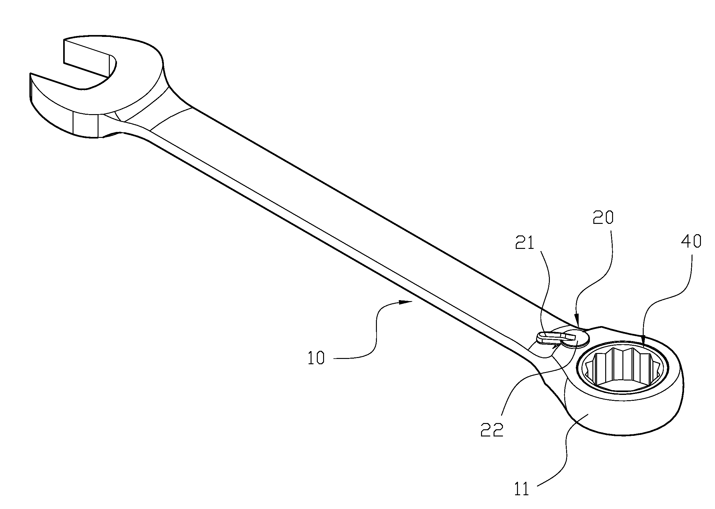
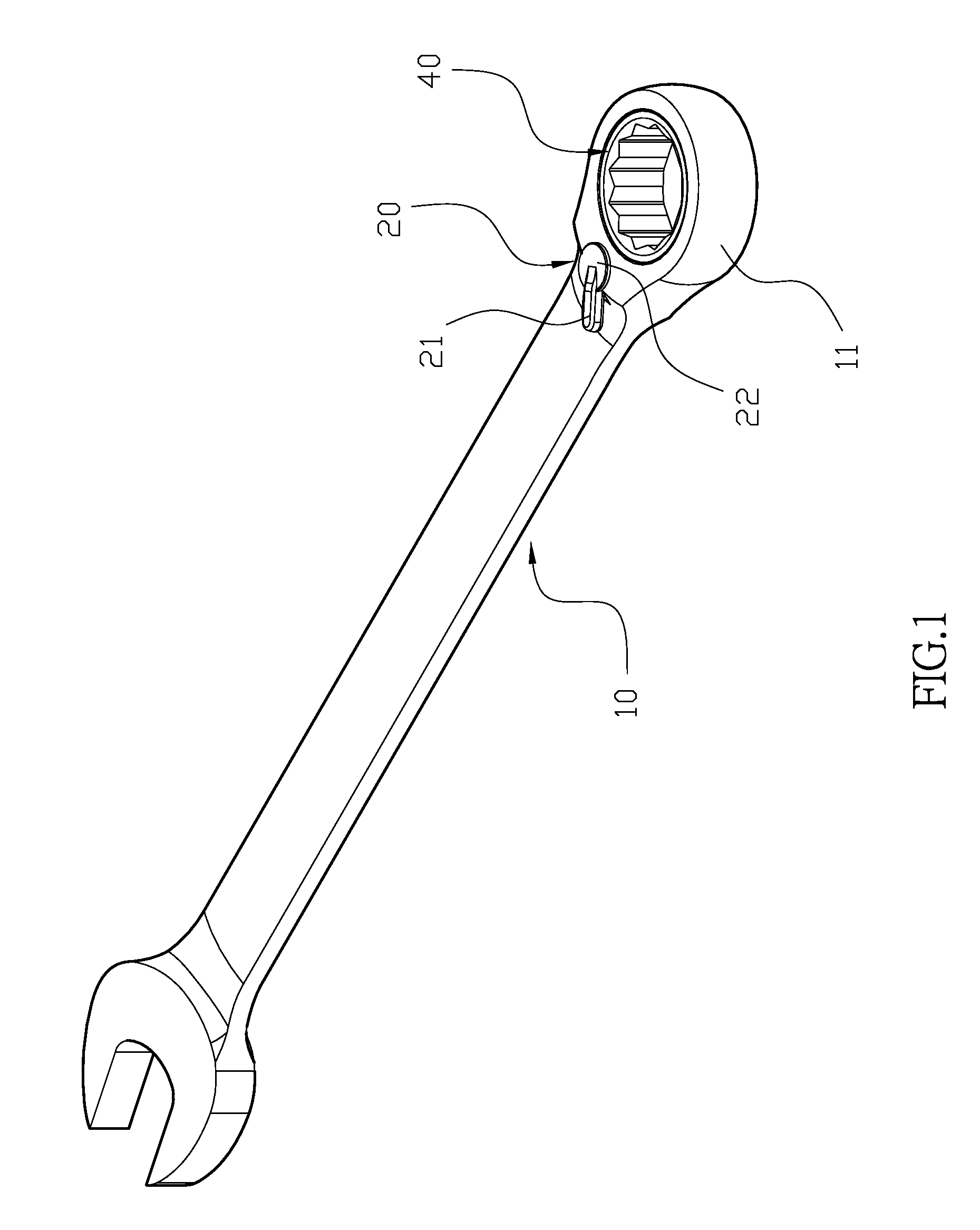
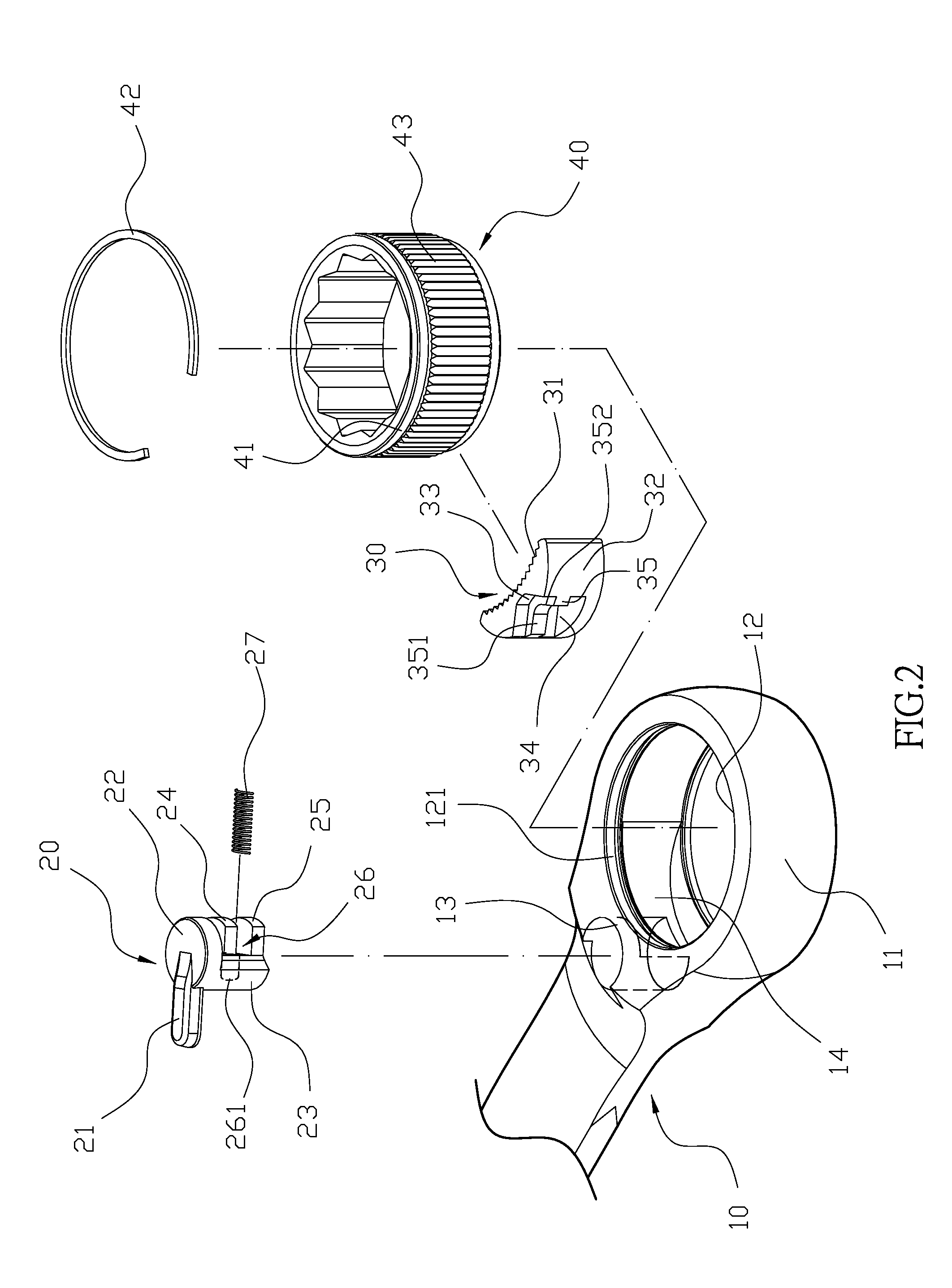
[0032]As illustrated in FIGS. 1 to 3, the novel reversible ratchet wrench of the present invention comprises a wrench body 10, a control member 20, a ratchet member 30, and a rotating member 40. The ratchet portion 11 is located at one end of the wrench body 10, which has an operation opening 12 and a round hole 13 wherein the operation opening 12 and the round hole 13 are connected via an arc-shaped ratchet slot 14. In addition, a fixing slot 121 is located at the top edge of the inner surface of the operation opening 12 of the wrench body 10. The control member 20 has a shaft portion 21, and a round plate 22 that is attached to the front end of the shaft portion 21. The round plate 22 is extended downwards to form a half cylinder 23, and the ...
PUM
 Abstract
Description
Claims
Application Information