Circuit for interconnected direct current power sources

Active Publication Date: 2015-05-21
SOLAREDGE TECH LTD
View PDF5 Cites 33 Cited by
  • Summary
  • Abstract
  • Description
  • Claims
  • Application Information

AI Technical Summary

Benefits of technology

[0008]A. The output voltage of the power converter may be sensed. The control circuit may be configured to set the input power received at the input terminals of the power converter to a maximum power only at a predetermined output voltage point or output voltage range or at a predetermined output current point or output current range. Away from the predetermined output

Problems solved by technology

Since the maximum power point tracking is performed at the input of the power converter, the output voltage or current of the power converter is not fully constrained.
However, many commercially available inverter modules already include integrated MPPT tracking circuits designed for use with conventional photovoltaic distributed power systems that do not include individual MPPT tracking for each power source as described above.
However, since the control circuit maintains the photovoltaic panel at its maximum power point, the power output of the DC/DC converters ma

Method used


Image

  • Circuit for interconnected direct current power sources
  • Circuit for interconnected direct current power sources
  • Circuit for interconnected direct current power sources

Examples


Embodiment Construction

[0034]Reference will now be made in detail to embodiments, examples of which are illustrated in the accompanying drawings, wherein like reference numerals refer to the like elements throughout. The embodiments are described below to explain examples by referring to the figures.

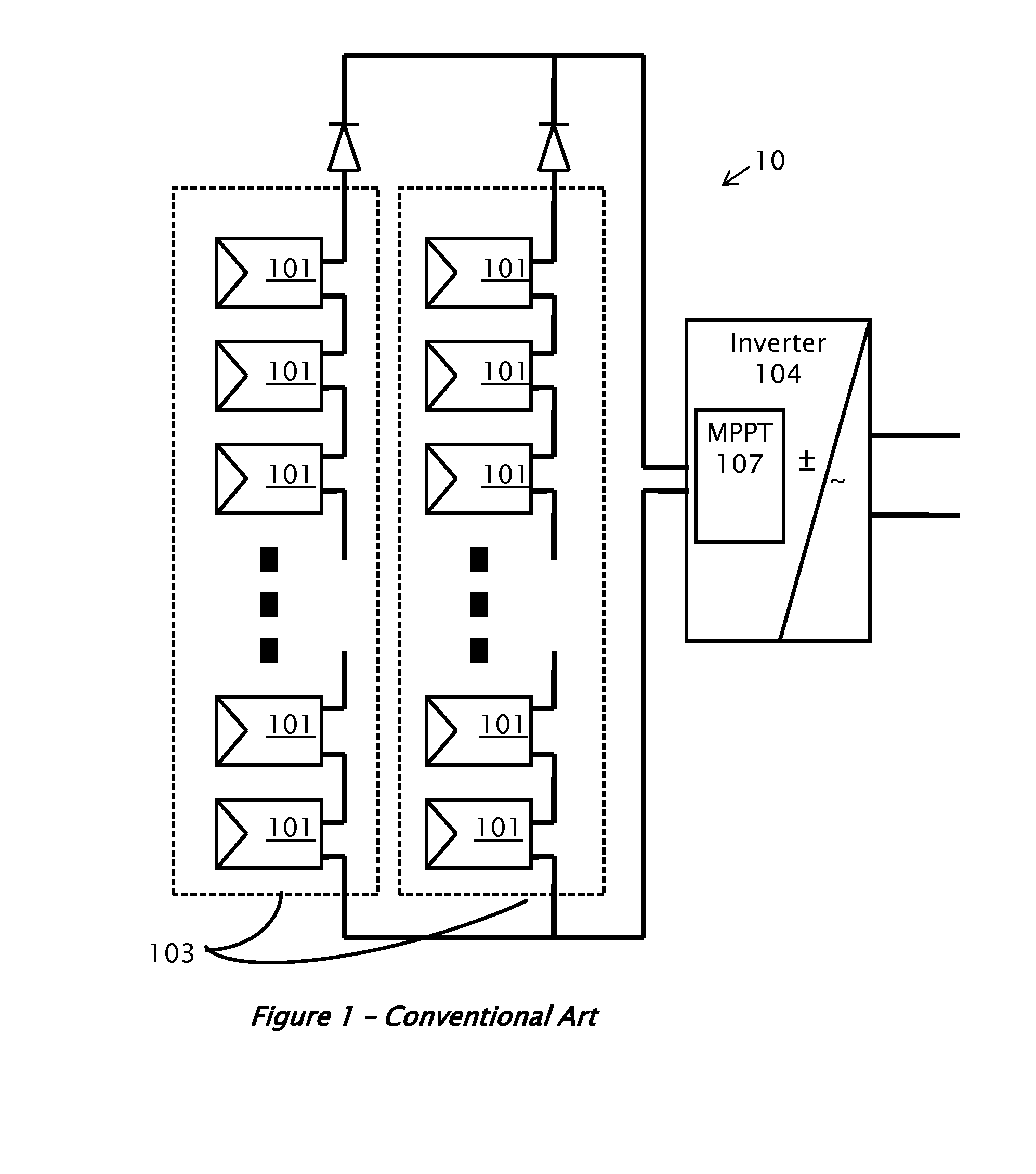
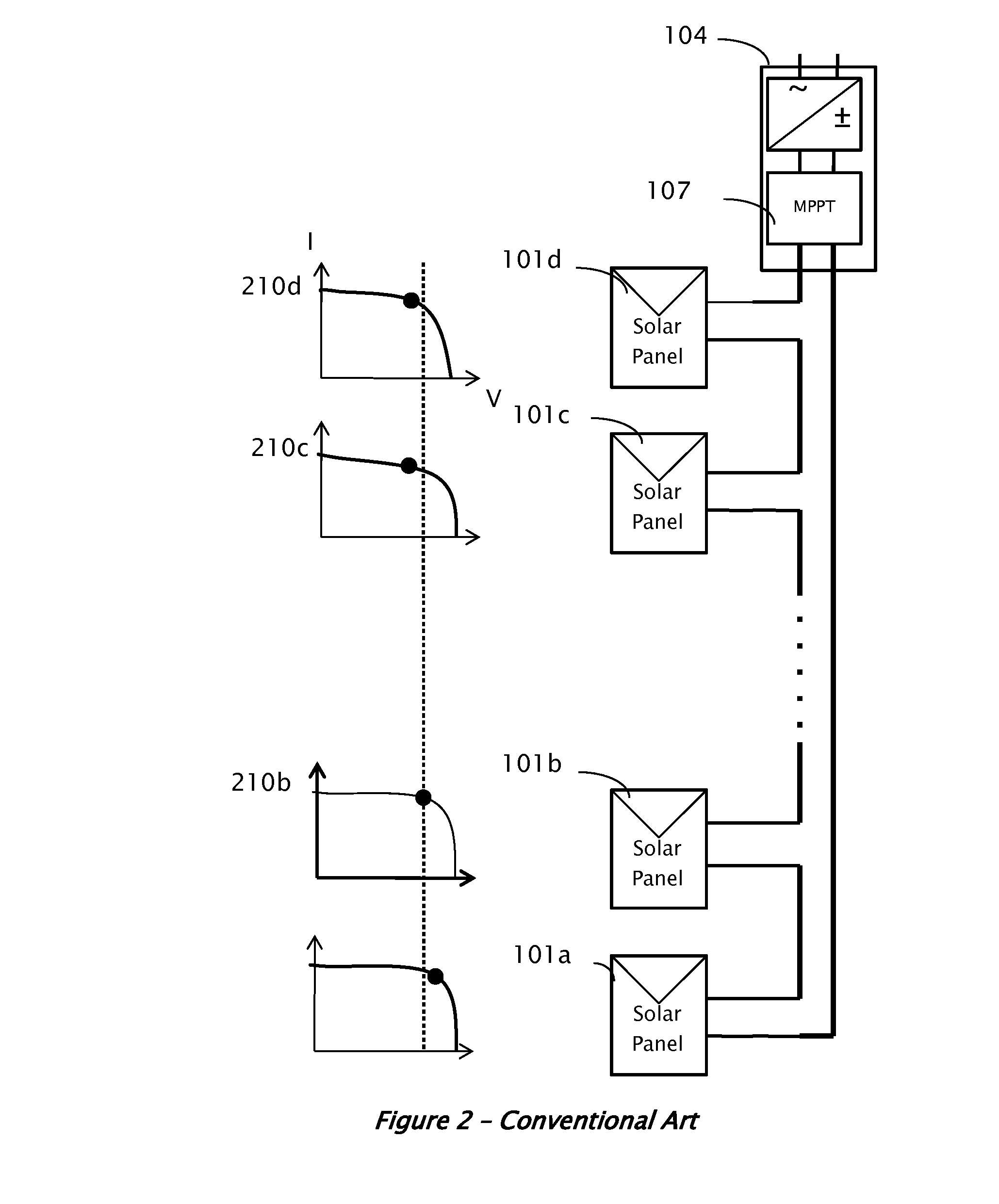
[0035]A conventional installation of solar power system 10 is illustrated in FIG. 1. Since the voltage provided by each individual solar panel 101 may be low, several panels may be connected in series to form a string of panels 103. For a large installation, when higher current may be utilized, several strings 103 may be connected in parallel to form the overall system 10. Solar panels 101 may be mounted outdoors, and their leads may be connected to a maximum power point tracking (MPPT) module 107 and then to an inverter 104. The MPPT 107 may be implemented as part of the inverter 104.

[0036]The harvested power from the DC sources may be delivered to the inverter 104, which converts the fluctuating direct-curre...


PUM


Abstract

Controlling a power converter circuit for a direct current (DC) power source is disclosed. The power converter may be operative to convert input power received from the DC power source to an output power and to perform maximum power point tracking of the power source. The power converter is adapted to provide the output power to a load that also performs maximum power point tracking.

Description

BACKGROUND[0001]Embodiments described in this application relate generally to control of power production from distributed current sources such as direct current (DC) power sources.[0002]Recent interest in renewable energy has led to increased research in systems for distributed generation of energy, such as photovoltaic cells (PV), fuel cells and batteries. Various inconsistencies in manufacturing may cause two otherwise identical sources to provide different output characteristics. Similarly, two such sources may react differently to operating conditions, e.g. load and / or environmental conditions, e.g. temperature. In installations, different sources may also experience different environmental conditions, e.g., in solar power installations some panels may be exposed to full sun, while others may be shaded, thereby delivering different power output. In a multiple battery installation, some of the batteries may age differently, thereby delivering different power output.BRIEF SUMMARY...

Claims


Application Information

Patent Timeline
IPC IPC(8): G05F1/67H02J1/00
CPCH02J1/00G05F1/67H02J3/385H02M7/49H02J2300/26H02J3/381Y02E10/56H02J3/38H02J3/388
Inventor ADEST, MEIRYOSCOVICH, ILANGALIN, YOAVSITY, ELAD
Owner SOLAREDGE TECH LTD
Why Eureka
Try Eureka