Scan region determining apparatus

a region determination and region technology, applied in the field of scan region determination apparatus, can solve the problems of inability to reliably determine the field of view, lack of robustness of determination technique used by the system, etc., and achieve the effect of more robust determination of the scan region

Active Publication Date: 2015-05-21
KONINKLJIJKE PHILIPS NV
View PDF8 Cites 17 Cited by
  • Summary
  • Abstract
  • Description
  • Claims
  • Application Information

AI Technical Summary

Benefits of technology

[0004]It is an object of the present invention to provide a scan region determining apparatus, a scan region determining method and a scan region determining computer program for determining a scan region of a subject to be scanned by a scanning system, which allows for a more robust determination of th...

Problems solved by technology

This determination of the field of view may not be reliable; especially if the localizer images show different objects and a field of view ...

Method used


Image

  • Scan region determining apparatus
  • Scan region determining apparatus
  • Scan region determining apparatus

Examples


Embodiment Construction

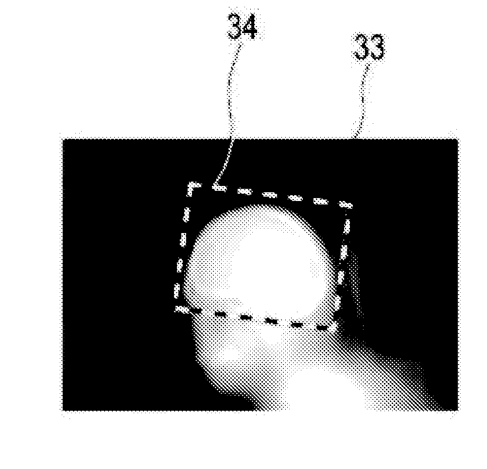
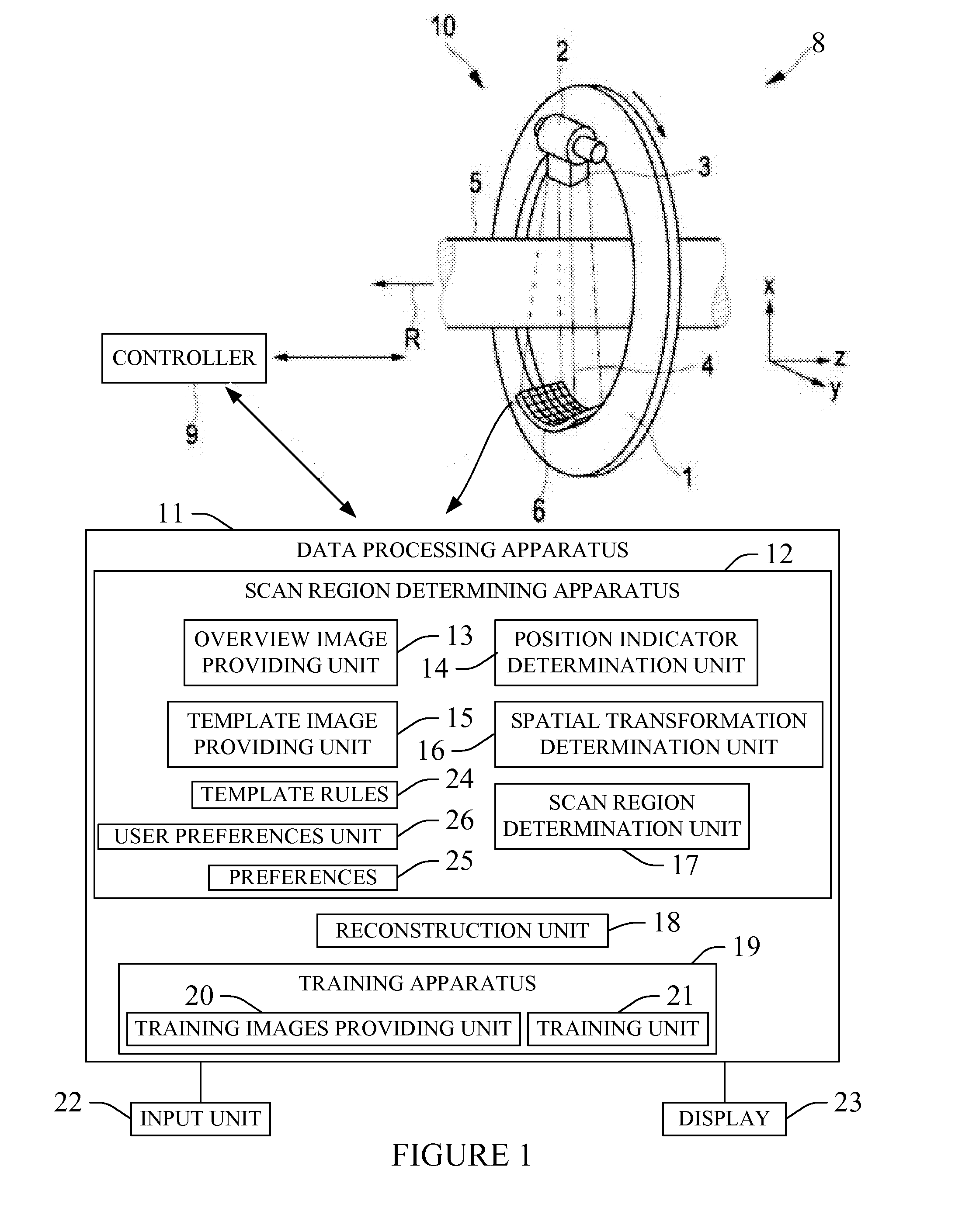
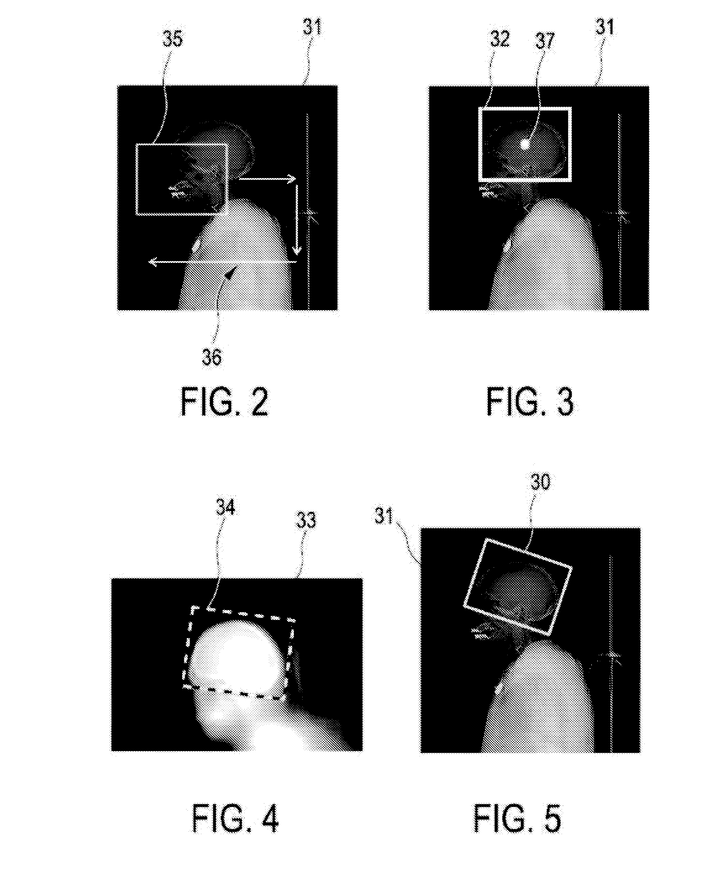
[0067]FIG. 1 shows schematically and exemplarily a scanning system for scanning a region of a subject. In this embodiment the scanning system 10 is a computed tomography system. The computed tomography system 10 comprises a gantry 1 which is capable of rotation around a rotational axis R which extends parallel to a z direction. A radiation source 2, which is an x-ray tube, is mounted on the gantry 1. The radiation source 2 is provided with a collimator 3, which forms, in this embodiment, a conical radiation beam 4 from the radiation generated by the radiation source 2. The radiation traverses a subject (not shown) such as a patient within an examination zone 5, which is cylindrical in this embodiment. After having traversed the examination zone 5 the radiation beam 4 is incident on a detection device 6, which comprises a two-dimensional detection surface. The detection device 6 is also mounted on the gantry 1. In another embodiment the collimator 3 can also be adapted to form anothe...


PUM


Abstract

A method includes displaying an iconic image of the human body and a list of predetermined anatomical regions. The method further includes displaying, in response to a user selected anatomical region, a scan box over a sub-portion of the iconic image. The method further includes receiving an input indicative of at least one of a scan box location of interest or a scan box geometry of interest, with respect to the anatomical region, of the first user. The method further includes at least one of re-locating or changing a geometry of the first initial scan box, in response thereto, creating a first user defined scan box for the first user. The method further includes creating a first transformation between a first template image representative of the selected anatomical region and the iconic image with the first user defined scan box for the first user, and storing the first transformation.

Description

CROSS REFERENCE TO RELATED APPLICATIONS[0001]This application is a Continuation-in-Part of PCT application Ser. No. PCT / IB2014 / 059248, filed Feb. 26, 2014, published as WO2014136017 A1 on Sep. 12, 2014, which claims the benefit of U.S. provisional application Ser. No. 61 / 773,429 filed Mar. 6, 2013, all of which are incorporated herein by reference.FIELD OF THE INVENTION[0002]The invention relates to a scan region determining apparatus, a scan region determining method and a scan region determining computer program for determining a scan region of a subject to be scanned by a scanning system. The invention relates further to a training apparatus, a training method and a training computer program for training the scan region determining apparatus and to a scanning system, a scanning method and a scanning computer program for scanning a region of the subject.BACKGROUND OF THE INVENTION[0003]US 2009 / 0290776 A1 discloses a system for automatically determining a field of view for performi...

Claims


Application Information

Patent Timeline
IPC IPC(8): G06T7/00
CPCG06T7/0044G06T2207/10081G06T2207/10104G06T7/0014G06T7/74G06F18/2411
Inventor SENEGAS, JULIENSAALBACH, AXELBERGTHOLDT, MARTINNETSCH, THOMASMAZURKEWITZ, PETER
Owner KONINKLJIJKE PHILIPS NV
Why Eureka
Try Eureka