
Scan region determining apparatus

a region determination and region technology, applied in the field of scan region determination apparatus, can solve the problems of inability to reliably determine the field of view, lack of robustness of determination technique used by the system, etc., and achieve the effect of more robust determination of the scan region

Active Publication Date: 2016-01-14
KONINKLJIJKE PHILIPS NV
View PDF2 Cites 3 Cited by
  • Summary
  • Abstract
  • Description
  • Claims
  • Application Information

AI Technical Summary

Benefits of technology

[0003]It is an object of the present invention to provide a scan region determining apparatus, a scan region determining method and a scan region determining computer program for determining a scan region of a subject to be scanned by a scanning system, which allows for a more robust determination of the scan region. It is a further object of the present invention to provide a training apparatus, a training method and a training computer program for training the scan region determining apparatus and a scanning system, a scanning method and a scanning computer program for scanning a scan region of a subject.
[0010]Since the spatial transformation determination unit determines a spatial transformation defining a registration of the overview image and the template image with respect to each other, wherein initially the overview image and the template image are registered by using the determined element position indicator being indicative of the position of the element of the subject to be scanned with respect to the overview image, a good initialization for the registration of the overview image and the template image with respect to each other is provided, which significantly reduces the probability of the registration procedure to be trapped in a local minimum. The registration and thus the determination of the spatial transformation are therefore very robust and allow for a robust determination of the final scan region by projecting the template scan region onto the overview image by using the determined spatial transformation. Moreover, since the registration of the overview image and the template image with respect to each other is well initialized based on the determined element position indicator being indicative of the position of the element of the subject to be scanned with respect to the overview image, the determination of the spatial transformation and hence of the final scan region can be relatively fast.
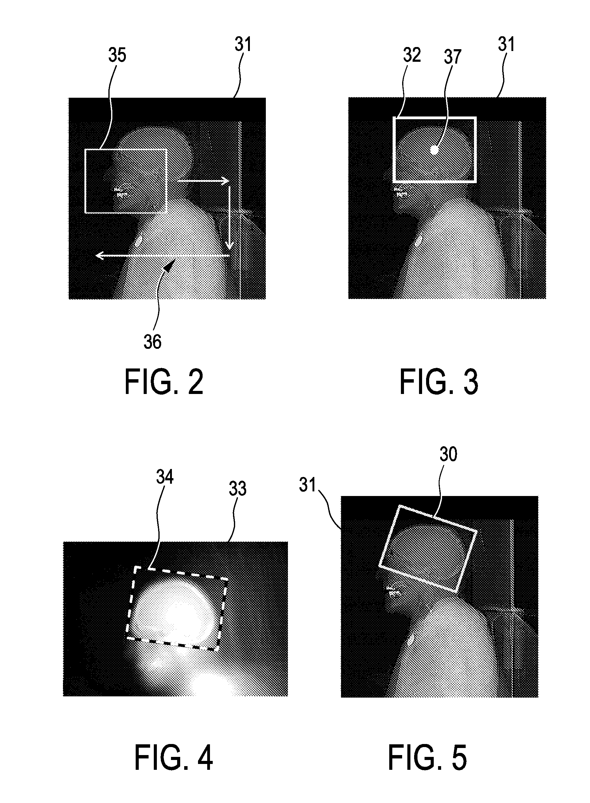
[0022]It is also preferred that the element position indicator determination unit is adapted to use a Viola-Jones algorithm for determining the element position indicator, in particular, the center of the element in the overview image and the intermediate scan region including the element to be scanned. The Viola-Jones algorithm has preferentially been trained by using a database of training overview images, in which a training scan region, which may have been added by hand, is already present. In the training overview images the training scan regions enclose the respective element, for instance, the respective organ, or a portion of the respective element. The Viola-Jones algorithm is very fast, for instance, it may require only a few milliseconds on a standard personal computer, thereby further increasing the speed of determining the scan region.
[0023]It is further preferred that the element position indicator determination unit is adapted to a) use an element position indicator determination algorithm for determining the element position indicator, b) provide element position indicator determination rules for selecting a most likely element position indicator, if the element position indicator determination algorithm revealed several possible element position indicators, and c) apply the element position indicator determination rules to the determined several possible element position indicators for determining the element position indicator to be used by the spatial transformation unit. For instance, the element position indicator determination unit can be adapted to determine for each element position indicator a score, wherein the element position indicator determination rules can defined that the element position indicator with the highest score should be selected. The score can be a direct outcome of the element position indicator determination algorithm. The score can also be determined in another way. For example, it can be determined depending on a grouping of spatially adjacent element position indicators. The score is, for instance, a probability or confidence value. Using the element position indicator determination rules can improve the accuracy of the determination of the element position indicator.
[0024]In an embodiment the spatial transformation determination unit is adapted to apply an intensity based registration algorithm to the overview image and the template image for determining the spatial transformation, wherein the image intensity based registration algorithm is initialized based on the determined element position indicator being indicative of the position of the element of the subject to be scanned with respect to the overview image. Image intensity based registration algorithms like a registration algorithm based on a cross correlation of the overview image and the template image are rather robust with respect to some degree of dissimilarity between the two images, which may be present in case of image artifacts, metal implants, unusual patient positioning, et cetera. Using an intensity based registration algorithm can therefore further improve the robustness of the determination of the scan region.

Problems solved by technology

This determination of the field of view may not be reliable, especially if the localizer images show different objects and a field of view should be determined with respect to a certain one of these objects.
The determination technique used by the system may therefore lack robustness.

Method used


Image

  • Scan region determining apparatus
  • Scan region determining apparatus
  • Scan region determining apparatus

Examples


Embodiment Construction

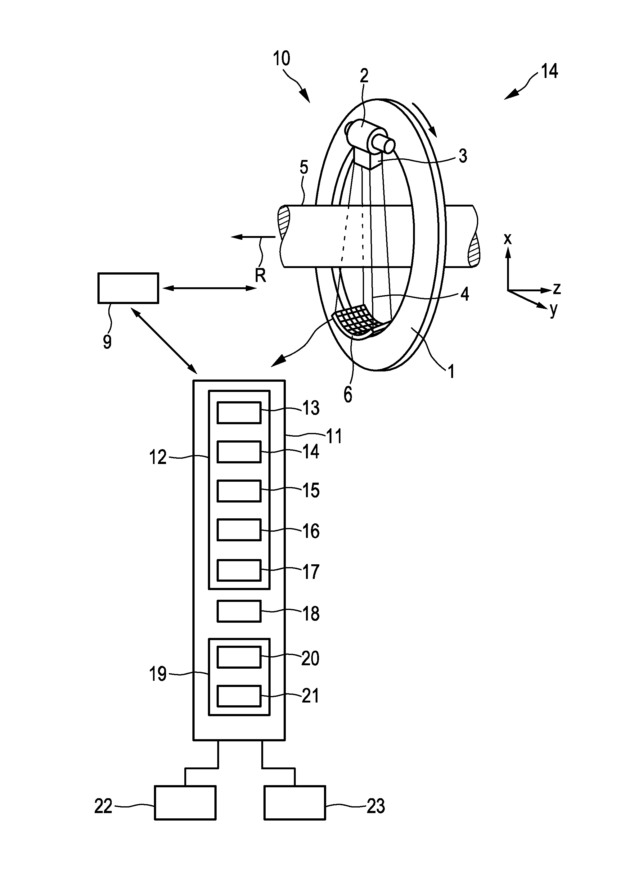
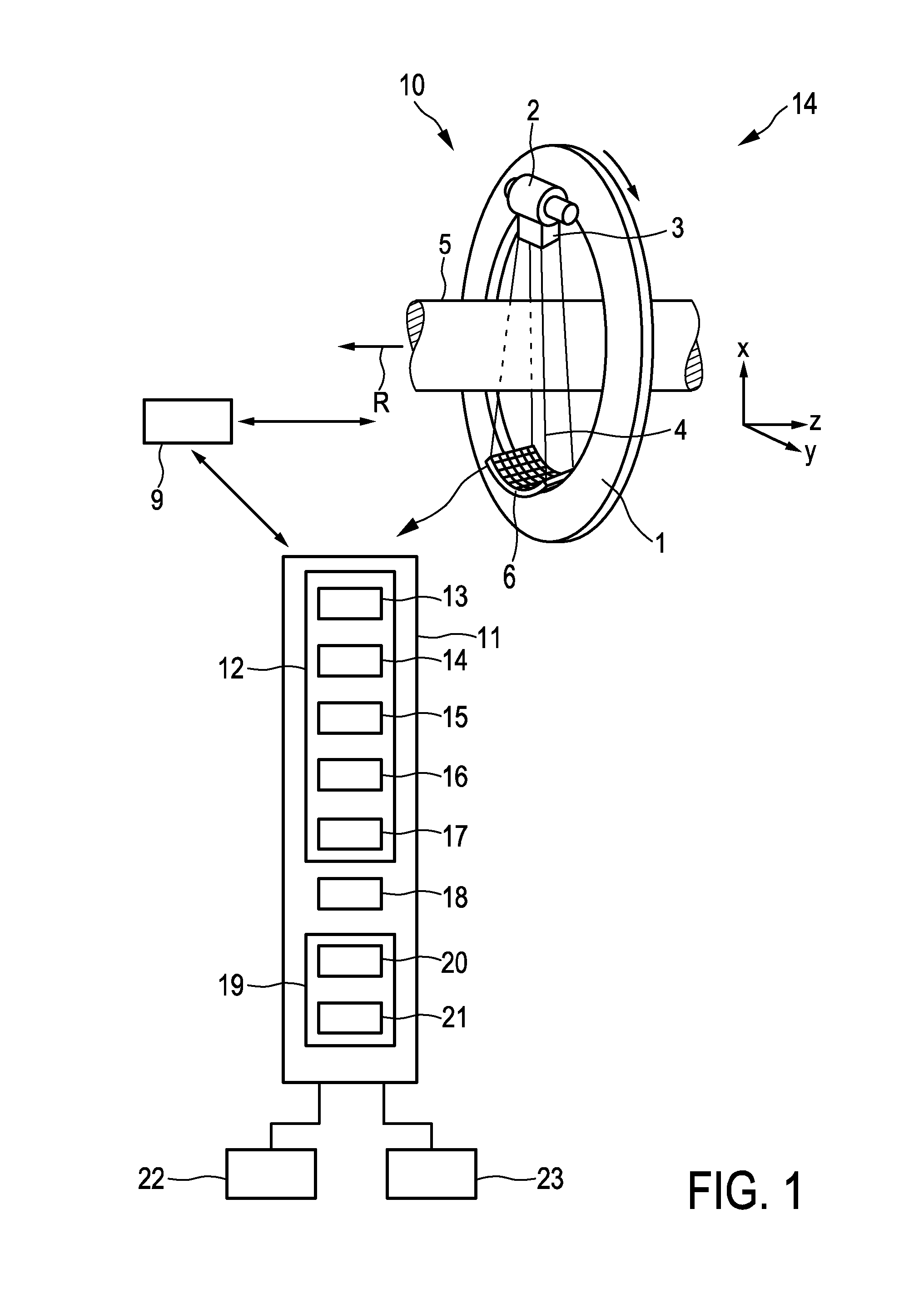
[0062]FIG. 1 shows schematically and exemplarily a scanning system for scanning a region of a subject. In this embodiment the scanning system 10 is a computed tomography system. The computed tomography system 10 comprises a gantry 1 which is capable of rotation around a rotational axis R which extends parallel to a z direction. A radiation source 2, which is an x-ray tube, is mounted on the gantry 1. The radiation source 2 is provided with a collimator 3, which forms, in this embodiment, a conical radiation beam 4 from the radiation generated by the radiation source 2. The radiation traverses a subject (not shown) such as a patient within an examination zone 5, which is cylindrical in this embodiment. After having traversed the examination zone 5 the radiation beam 4 is incident on a detection device 6, which comprises a two-dimensional detection surface. The detection device 6 is also mounted on the gantry 1. In another embodiment the collimator 3 can also be adapted to form anothe...


PUM


Abstract

The invention relates to a scan region determining apparatus (12) for determining a scan region of a subject to be scanned by a scanning system (10) like a computed tomography system. A spatial transformation defining a registration of an overview image and a template image with respect to each other is determined, wherein initially the overview image and the template image are registered by using an element position indicator being indicative of a position of an element of the subject with respect to the overview image. A template scan region is defined with respect to the template image, wherein a final scan region is determined by projecting the template scan region onto the overview image by using the determined spatial transformation. The registration and thus the determination of the spatial transformation are very robust, which improves the quality of determining the final scan region.

Description

FIELD OF THE INVENTION[0001]The invention relates to a scan region determining apparatus, a scan region determining method and a scan region determining computer program for determining a scan region of a subject to be scanned by a scanning system. The invention relates further to a training apparatus, a training method and a training computer program for training the scan region determining apparatus and to a scanning system, a scanning method and a scanning computer program for scanning a region of the subject.BACKGROUND OF THE INVENTION[0002]US 2009 / 0290776 A1 discloses a system for automatically determining a field of view for performing a subsequent medical imaging study. The system comprises a medical imaging device for acquiring one or more two-dimensional localizer images and for performing a subsequent three-dimensional medical imaging study. The system further comprises a body mask generation unit for thresholding the localizer images and identifying a largest connected co...

Claims


Application Information

Patent Timeline
Patent Type & Authority Applications(United States)
IPC IPC(8): G06T7/00G06K9/62
CPCG06T7/0014G06T7/0044G06T2207/10104G06T2207/10081G06K9/6269G06T7/74G06F18/2411
Inventor SENEGAS, JULIENSAALBACH, AXELBERGTHOLDT, MARTINNETSCH, THOMASMAZURKEWITZ, PETER
Owner KONINKLJIJKE PHILIPS NV
Learn More