Developing apparatus

Active Publication Date: 2015-05-21
CANON KK
View PDF5 Cites 22 Cited by
  • Summary
  • Abstract
  • Description
  • Claims
  • Application Information

AI Technical Summary

Benefits of technology

[0007]The primary object of the present invention, which relates to a developing apparatus which uses a return screw to regulate the amount by which developer is discharged, is to provide a de

Problems solved by technology

As the developer in the developing device (1) is continuously stirred for a subs

Method used


Image

  • Developing apparatus
  • Developing apparatus
  • Developing apparatus

Examples


embodiment 1

Effects of Embodiment 1

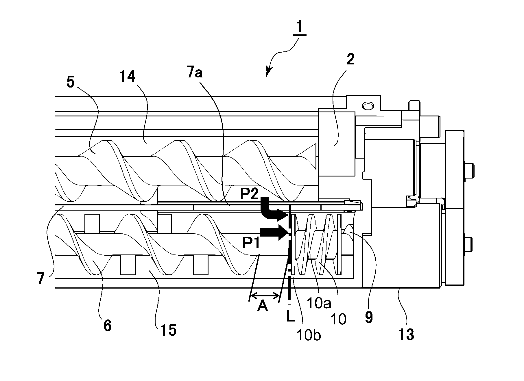
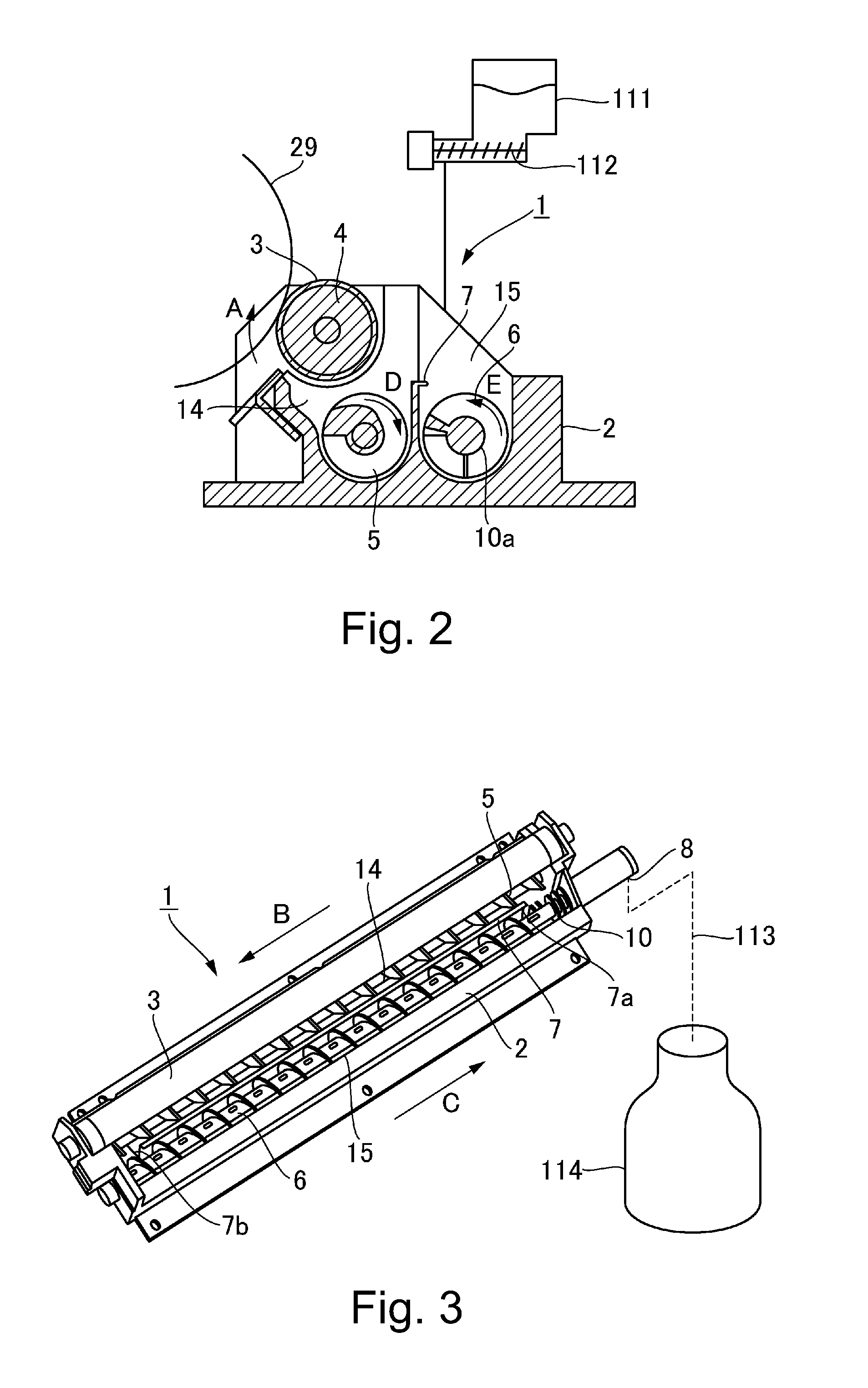
[0078]In recent years, carrier has been improved in terms of its deterioration attributable to the operation of the developing device 1, and also, has been reduced in the amount of toner required for image formation. With the presence of such background, it is desired to reduce the amount by which developer is recovered and stored in the recovery container (114 in FIG. 3), by reduction in the amount by which carrier is supplied to the developing device 1, in order to reduce the image forming apparatus 100 in operational cost, and also, the amount of waste. However, as the amount by which carrier is supplied to a developing device (1) is reduced, the changes in the amount of the developer in the developer container (2), which is attributable to the periodic developer leakage, increases. In comparison, in the case of the developing device 1 in the first embodiment, the periodic developer leakage attributable to the rotation of the return screw 10 is unlikely to ...

embodiment 2

[0084]FIG. 13 is a plan view of the adjacencies of the return screw of the developing device in the second embodiment of the present invention. FIG. 14 is a perspective view of the adjacencies of the return screw of the developing device in the second embodiment. FIG. 15 is a drawing for describing a return screw provided with a tapered portion. The developing device in the second embodiment is the same in structure as the developing device 1 in the first embodiment, except that its return screw 10 is provided with a tapered portion. Therefore, the structural components, and portions thereof, of the developing device 1 shown in FIGS. 13-15, which are the same in structure as the counterparts shown in FIGS. 9 and 10, are given the same referential codes as those given to the counterparts, and are not described here in order not to repeat the same descriptions.

[0085]Referring to FIG. 13, in the second embodiment, the return screw 10 is provided with a regulatory portion 10d, which is ...


PUM


Abstract

A developing apparatus including a first chamber; a second chamber forming a circulation path for the developer; a rotatable shaft in the first chamber; a first blade provided on the rotation shaft to feed the developer in a predetermined direction in the first chamber; a second blade provided on the rotation shaft to feed the developer fed by the first blade in a direction opposite the predetermined direction; a discharging portion provided downstream of the second blade to discharge the developer in the first chamber; and a regulating member having a regulating surface continuously extending in a rotational moving direction of the rotation shaft, the regulating member being provided on the rotation shaft in a region between the first blade and the second blade, a region connecting with a downstream end of the first blade, or a connecting with a downstream end of the second blade.

Description

FIELD OF THE INVENTION AND RELATED ART[0001]The present invention relates to a developing apparatus which is mounted in an electrophotographic image forming apparatus or the like to develop an electrostatic image on an image bearing member into a toner image, with the use of developer which contains toner and carrier.[0002]There have been widely used an image forming apparatus such as a copying machine, a printer, and a facsimile, the developing device of which develops an electrostatic image formed on an image bearing member such as a photosensitive drum, into a toner image, with the use of developer which contains toner and carrier.[0003]Referring to FIG. 3, the background technologies of an image forming apparatus of the abovementioned type is described. A developing device (1) circularly moves developer through a development chamber (14) and a stirring chamber (15), which are in connection to each other through openings (7a, 7b), by rotating a conveyance screw (5) and a stirring...

Claims


Application Information

Patent Timeline
IPC IPC(8): G03G15/08
CPCG03G15/0812G03G15/0893G03G21/10G03G2215/083
Inventor TSUKIJIMA, HISASHIISHIDA, YUSUKEIIDA, TAKANORI
Owner CANON KK
Why Eureka
Try Eureka