Permanent magnet rotor

Inactive Publication Date: 2015-05-28
JOHNSON ELECTRIC INTERNATIONAL AG
View PDF10 Cites 4 Cited by
  • Summary
  • Abstract
  • Description
  • Claims
  • Application Information

AI Technical Summary

Benefits of technology

The patent aims to address the issue of magnetic leakage in an IPM rotor for a brushless motor. The invention proposes a design that gradually reduces the radial thickness of each connector, resulting in a rotor with a gradually reduced outer diameter at each connector. This design also reduces the number of connecting arms, which further improves the motor performance by reducing magnetic leakage.

Problems solved by technology

However, the above brushless motor suffers from significant magnetic leakage, which affects the performance of the motor.

Method used


Image

  • Permanent magnet rotor
  • Permanent magnet rotor
  • Permanent magnet rotor

Examples


Embodiment Construction

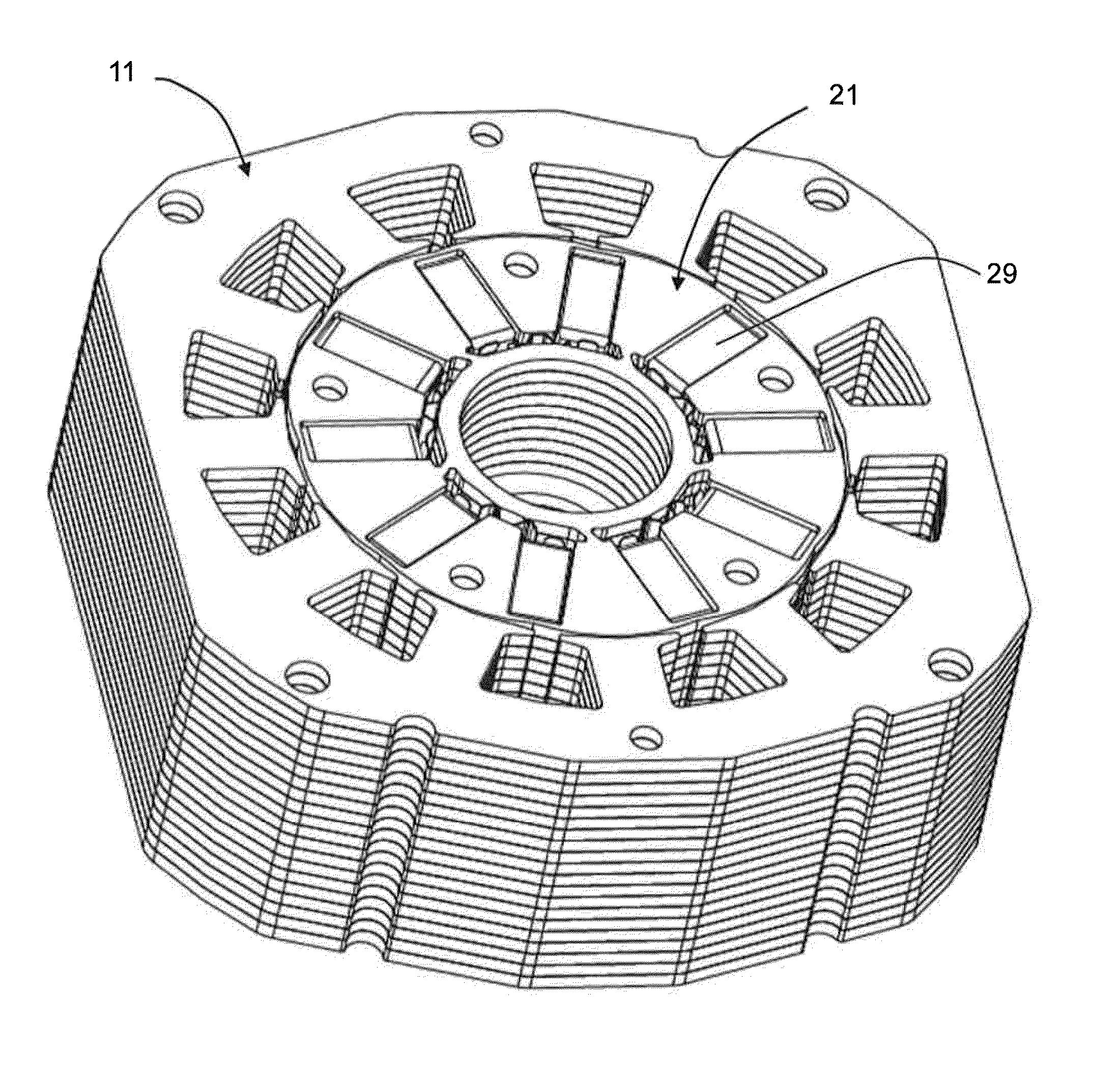
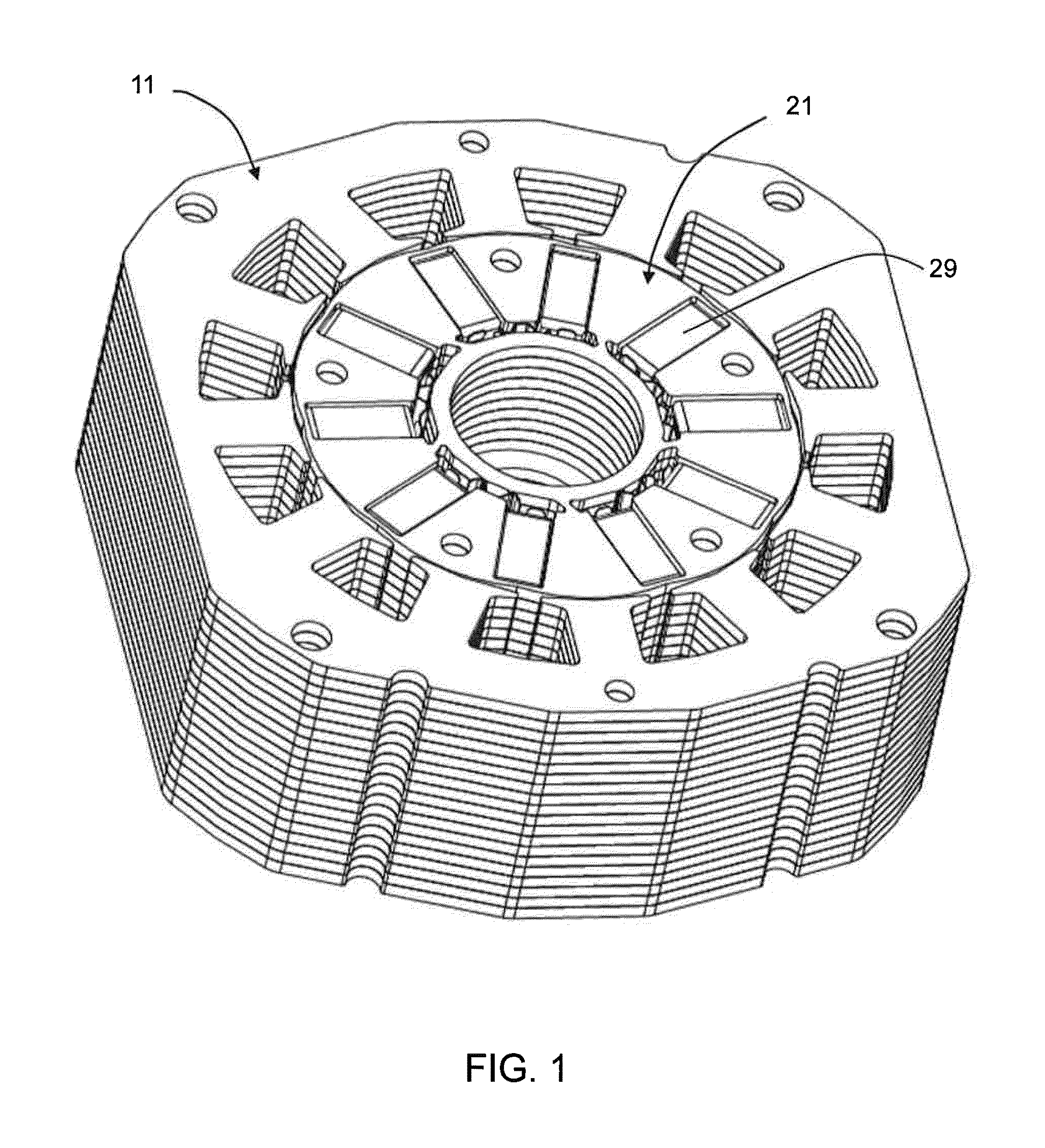
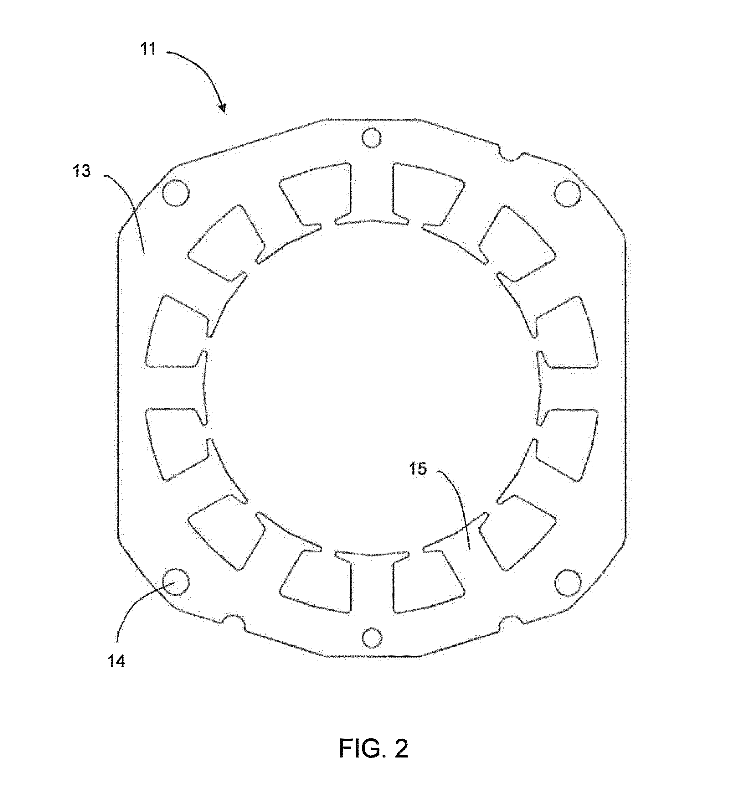
[0028]Referring to FIGS. 1 and 2, a brushless direct current motor in accordance with one embodiment of the present invention includes a stator and a rotor. The stator includes a stator core 11, having an annular ring or yoke 13 from which teeth 15 extend radially inward. A winding (not shown) is wound about the teeth 15 of the stator core 11, and end caps (not shown) are mounted to ends of the stator core 11. The end caps support bearings for mounting the shaft. Holes 14 extend through the yoke 13 and may be used for fixing the end caps or for mounting the motor.

[0029]The rotor includes a shaft (not shown), a rotor core 21 fixed to the shaft, and a plurality of permanent magnets 29 embedded in the rotor core 21. The shaft of the rotor is mounted to the end caps via bearings (not shown) and thereby is rotatably connected with the stator.

[0030]As shown more clearly in FIGS. 3 and 4, the rotor core 21 includes an inner annular portion 22 and an outer annular portion (not labeled). The...


PUM


Abstract

A rotor for a brushless motor includes a shaft, a rotor core and a number of permanent magnets. The rotor core includes inner and outer annular portions. The inner annular portion has a central hole for receiving the shaft. The outer annular portion includes a number of sector segments arranged in a ring, with adjacent sector segments defining a slot there between for receiving a corresponding permanent magnet. Radially outer ends of adjacent sector segments are interconnected by a connector. The sector segments include first sector segments and second sector segments arranged alternately. The first sector segments are separated from the inner annular portion. The second sector segments are each connected to the inner annular portion by connecting arms.

Description

CROSS REFERENCE TO RELATED APPLICATIONS[0001]This non-provisional patent application claims priority under 35 U.S.C. §119(a) from Patent Application No. 201310627892.3 filed in The People's Republic of China on Nov. 28, 2013, the entire contents of which are hereby incorporated by reference.FIELD OF THE INVENTION[0002]This invention relates to a brushless electric motor and in particular, to a permanent magnet rotor for a brushless motor, being of the internal permanent magnet (IPM) type.BACKGROUND OF THE INVENTION[0003]Brushless motors include a rotor generally having a shaft, a rotor core fixed to the shaft, and permanent magnets fixed to the rotor core. In an IPM type rotor, the magnets are embedded in the rotor core rather than being fixed to the outer surface of the rotor core. The core of the IPM rotor includes an inner annular portion and an outer annular portion. The inner annular portion has a central through hole for mounting the shaft. The outer annular portion includes a...

Claims


Application Information

Patent Timeline
IPC IPC(8): H02K1/27H02K21/14
CPCH02K21/14H02K1/2706H02K1/28H02K29/00H02K29/03H02K1/2773
Inventor LI, YUEZHOU, CHUI YOUCHAI, JIEPOON, KWONG YIPXIAO, SAN YUANHE, HAN
Owner JOHNSON ELECTRIC INTERNATIONAL AG
Why Eureka
Try Eureka