
Radar using hermetic transforms

a hermetic transformation and radar technology, applied in the field of radar, can solve problems such as the presence of observed time delay

Active Publication Date: 2015-05-28
HOBBIT WAVE
View PDF3 Cites 24 Cited by
  • Summary
  • Abstract
  • Description
  • Claims
  • Application Information

AI Technical Summary

Benefits of technology

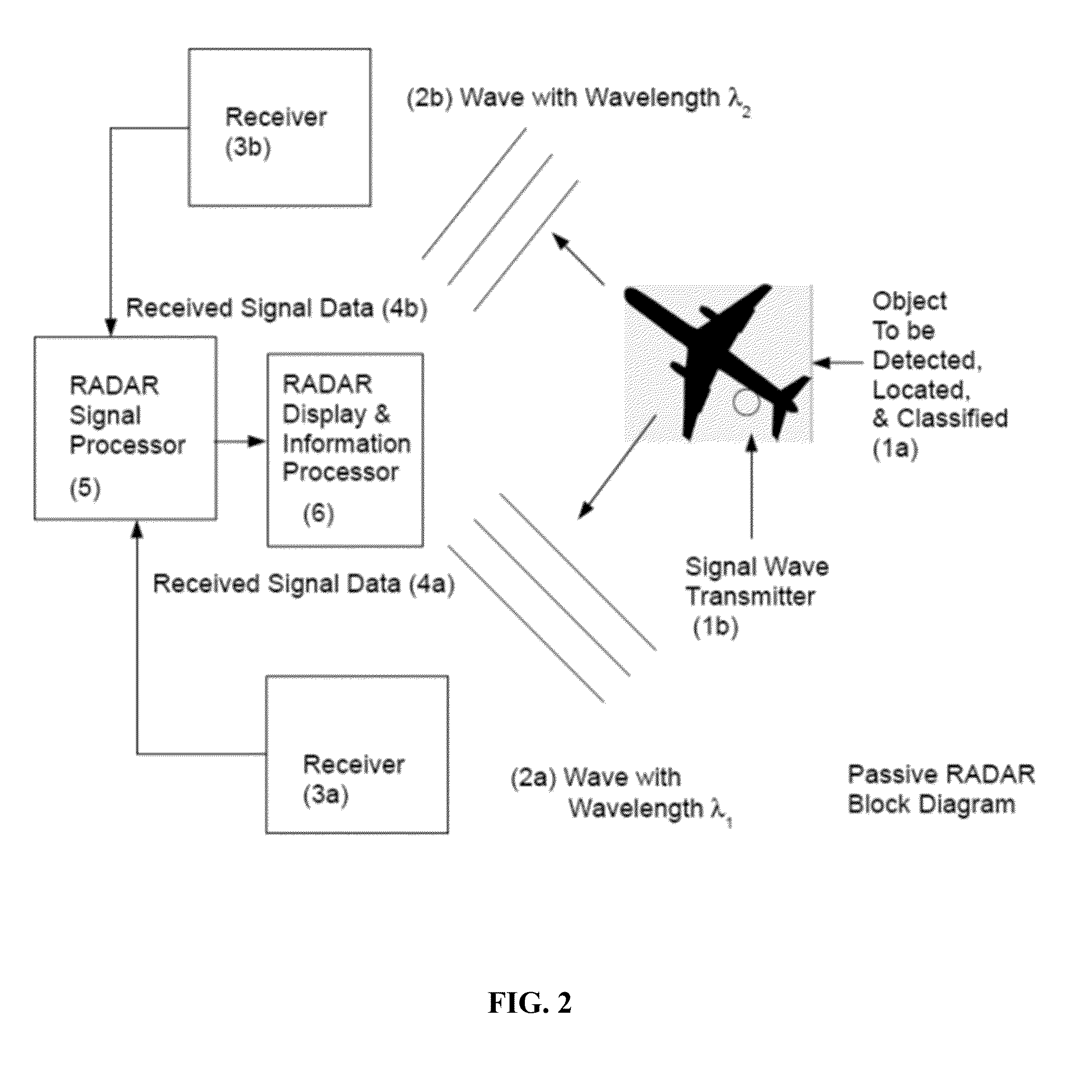
This patent is about a method for improving radar systems by using the Hermetic Transform to better determine the time, Doppler, and angle of objects detected by the radar. This method also enhances the signal-to-noise ratio by improving beamforming. The patent also describes the use of the Hermetic Transform in passive radar systems, where only RADAR receivers are required. Overall, this patent aims to improve the accuracy and reliability of radar systems for various applications.

Problems solved by technology

In addition, the finite speed of light c, causes an observable time delay to be present in receiving the echo from target, which allows distance to the target to also be inferred.

Method used


Image

  • Radar using hermetic transforms
  • Radar using hermetic transforms
  • Radar using hermetic transforms

Examples


Embodiment Construction

[0012]This disclosure includes application of the Hermetic Transform disclosed in U.S. Pat. No. 8,064,408 (issued Nov. 22, 2009), and U.S. Pat. No. 8,559,456 (issued Oct. 15, 20013), each of which is expressly incorporated herein for all purposes, to aspects of the RADAR signal processing problem in order to provide improved time, Doppler, and angle determination, as well to enhanced time, Doppler, and angle filtering (beamforming) to improve signal-to-noise ratio (SNR). The incorporated patent also identifies structures (processors, memory, etc.) that can be used to implement such systems.

[0013]The systems and methods described here improve upon these systems through the use of Hermetic Transform processing to achieve higher resolution in space, time, and frequency measurements, leading to enhanced object detection, localization, and classification. The present disclosure improves upon several aspects of RADAR, including: phased-array beam-forming (phased-array RADAR), Doppler filt...


PUM


Abstract

The systems and methods use Hermetic Transform processing to achieve higher resolution in space, time, and frequency measurements, leading to enhanced object detection, localization, and classification, and can improve several aspects of RADAR, including: phased-array beamforming, Doppler filter processing, pulse compression / replica correlation, and in the creation of higher resolution ambiguity function measurements for both multi-static active and passive RADAR.

Description

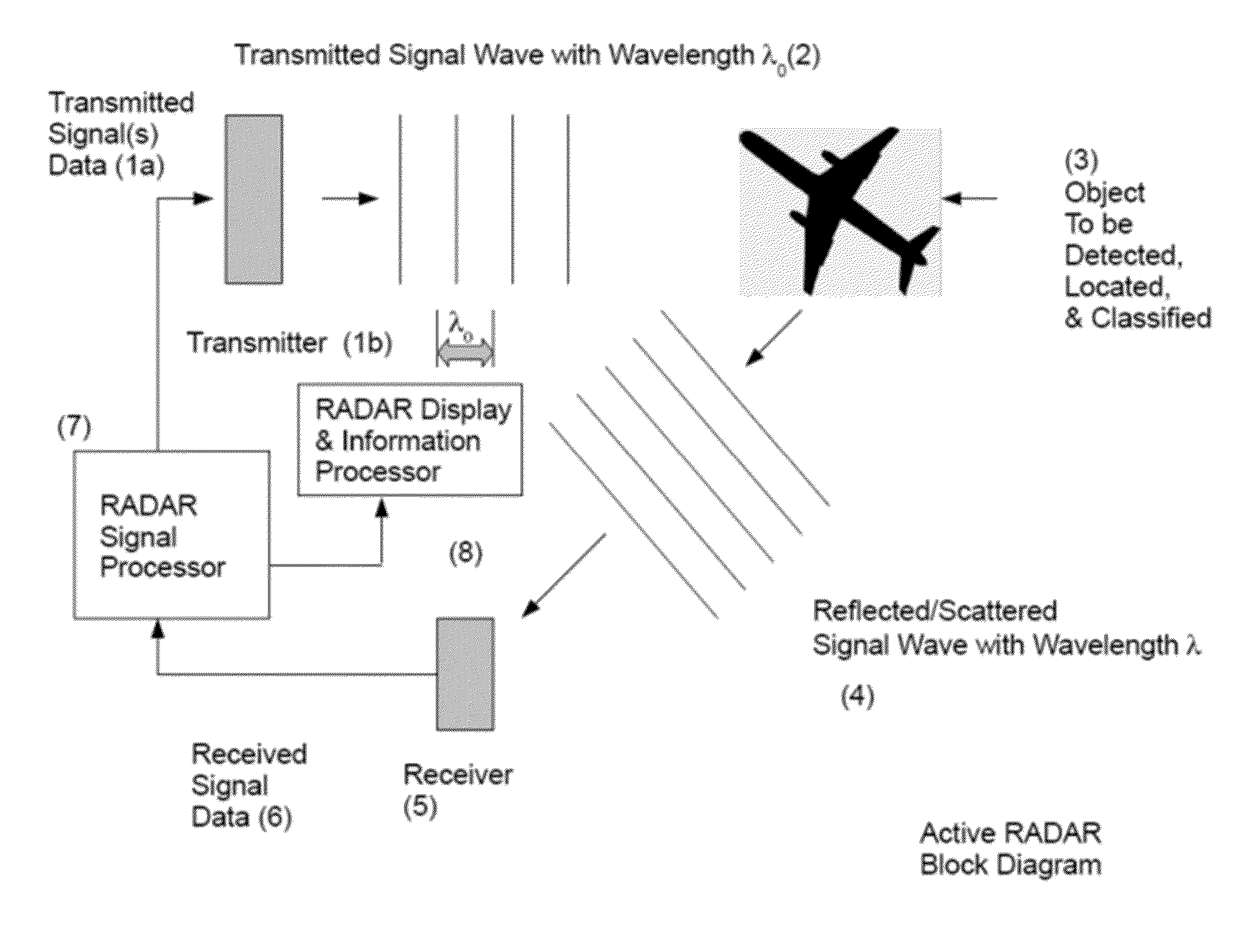
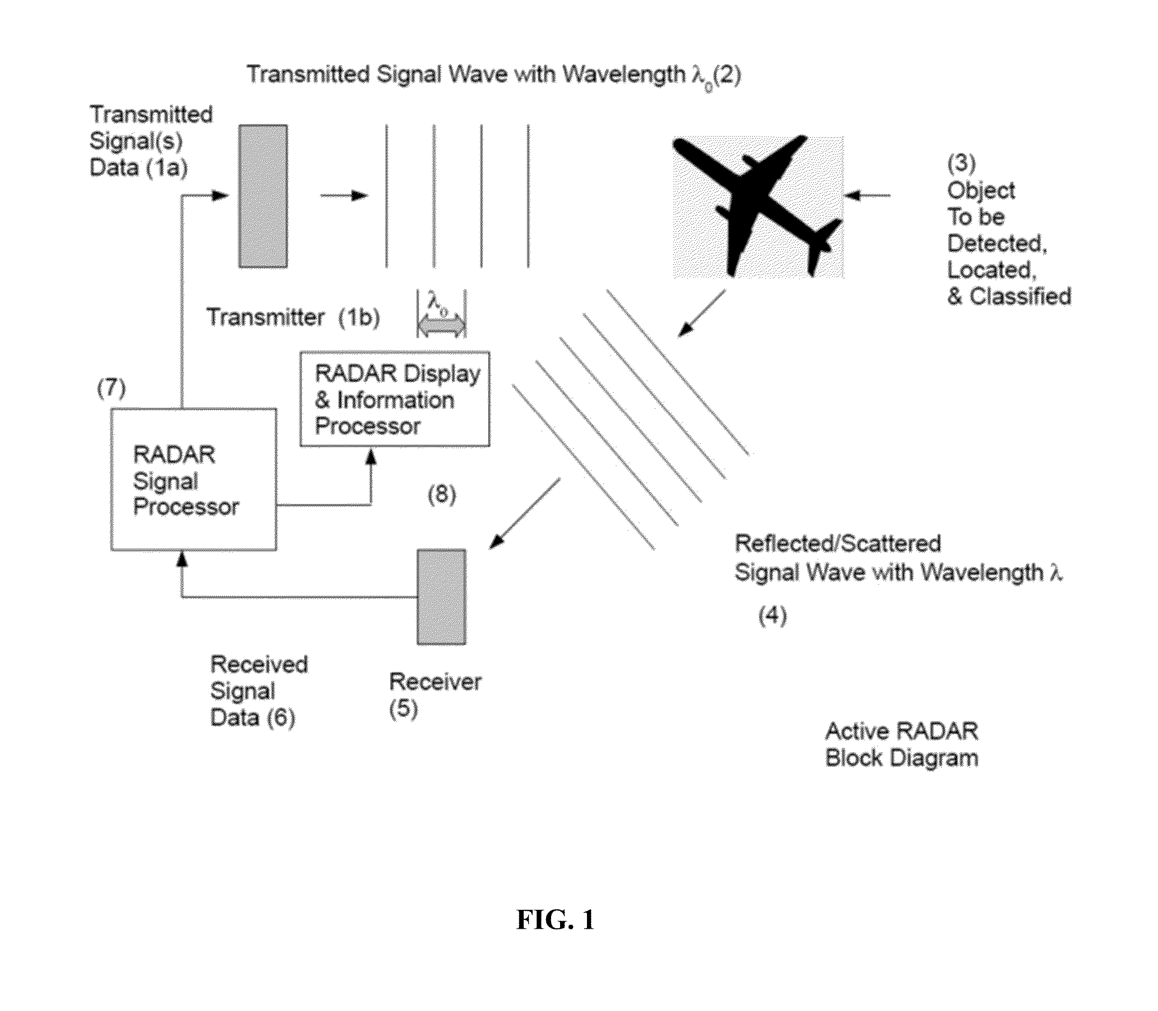
CROSS-REFERENCE[0001]This application claims priority under §119(e) to provisional application 61 / 907,715, filed Nov. 22, 2013, which is incorporated by reference.FIELD OF THE INVENTION[0002]This disclosure relates to the field of RADAR, and to other forms of object detection and location systems which derive from the principles of RADAR (such as SONAR, SODAR, LIDAR, and Medical Ultrasonography).BACKGROUND OF THE INVENTION[0003]Referring to FIG. 1, a purpose of RADAR is to accomplish detection, localization, and potentially classification of objects remotely. In active RADAR, a wave of electromagnetic energy 2 is launched from a transmission source 1a which derives the signals to be carried by the wave 1b from a RADAR Signal Processor 7. The transmitted wave propagates to the object (the “target”) 3 and is reflected or scattered by the object, returning an echo wave 4 to the RADAR Receiver 5. The receiver may, but need not, be co-located with the point of transmission.[0004]Assume a...

Claims


Application Information

Patent Timeline
Patent Type & Authority Applications(United States)
IPC IPC(8): G01S7/292G01S13/50G01S13/06
CPCG01S7/292G01S13/50G01S13/06G01S3/74G01S5/04G01S7/411G01S7/415G01S13/003G01S13/28G01S13/42G01S13/524G01S2013/0245
Inventor WOODSUM, HARVEY C.
Owner HOBBIT WAVE
Learn More