
Microphone

Active Publication Date: 2015-05-28
ELECTRONICS & TELECOMM RES INST
View PDF4 Cites 24 Cited by
  • Summary
  • Abstract
  • Description
  • Claims
  • Application Information

AI Technical Summary

Benefits of technology

The present invention improves the sensitivity of a microphone.

Problems solved by technology

The piezo-type microphone has many limitations in application due to a low bandwidth and a uniform characteristic of a voice band frequency.

Method used


Image

  • Microphone
  • Microphone
  • Microphone

Examples


Embodiment Construction

[0037]Exemplary embodiments of the present invention will be described with reference to the accompanying drawings so as to sufficiently understand constitutions and effects of the present invention. The present invention may, however, be embodied in different forms and should not be construed as limited to the embodiments set forth herein. Rather, these embodiments are provided so that this disclosure will be thorough and complete, and will fully convey the scope of the present invention to those skilled in the art. Further, the present invention is only defined by scopes of claims. A person with ordinary skill in the technical field of the present invention pertains will be understood that the present invention can be carried out under any appropriate environments.

[0038]In the following description, the technical terms are used only for explaining a specific exemplary embodiment while not limiting the present invention. The terms of a singular form may include plural forms unless ...


PUM


Abstract

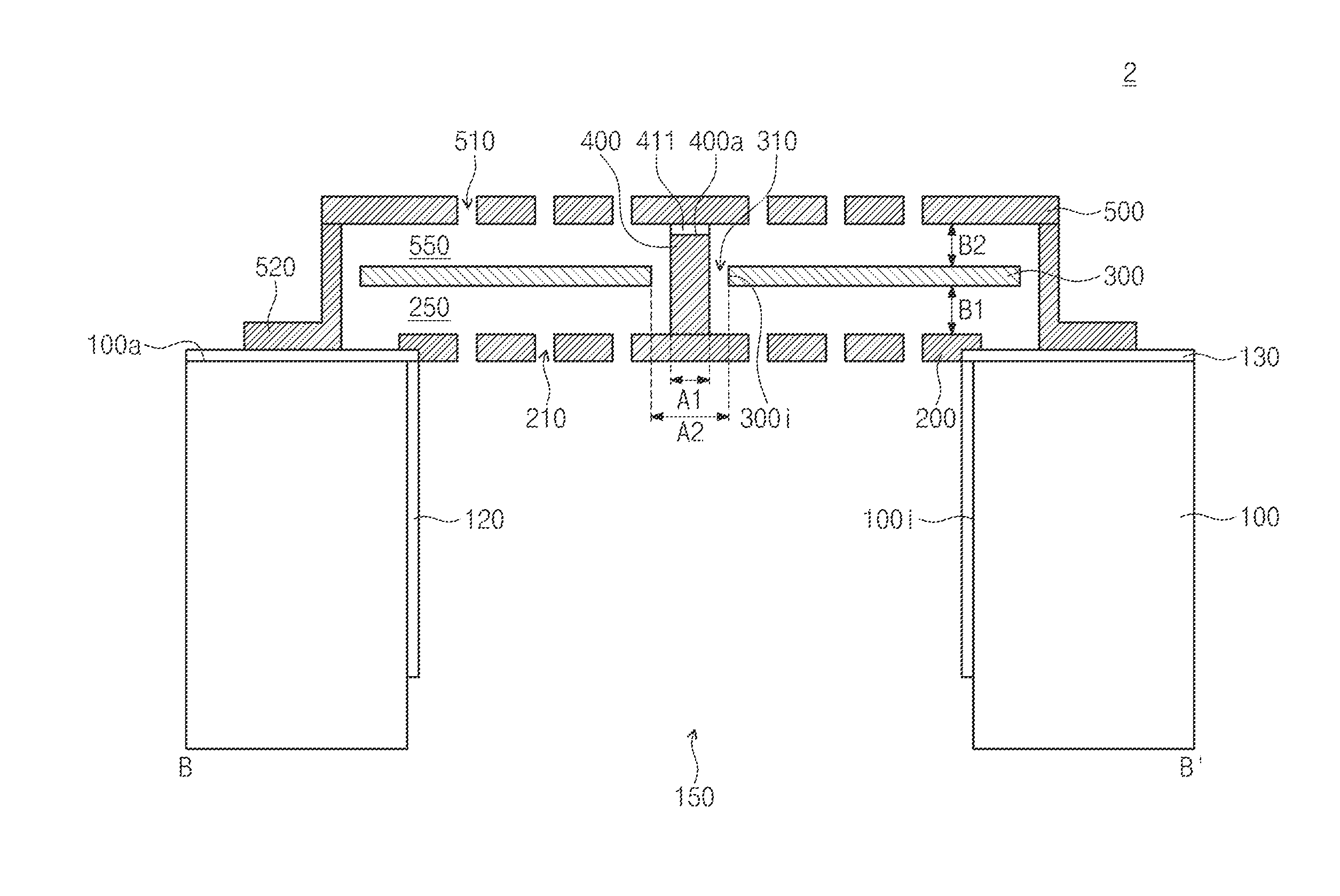
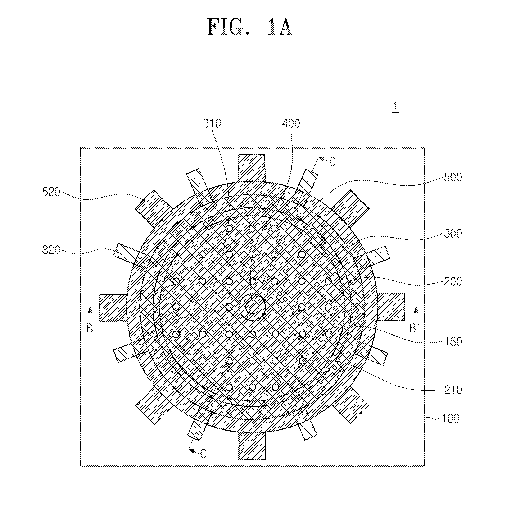
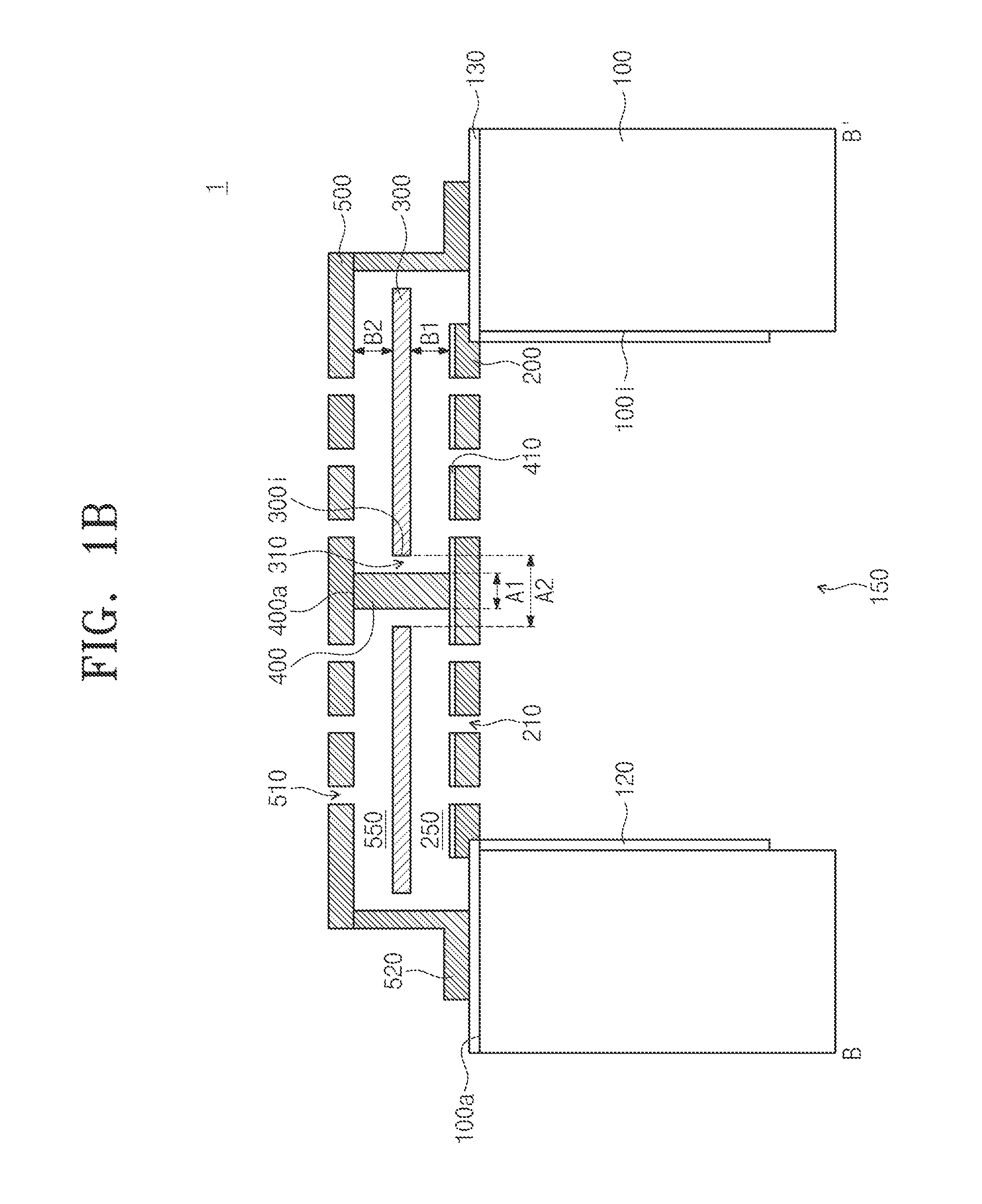
Provided is a microphone. The microphone includes a substrate including an acoustic chamber, a lower backplate disposed on the substrate, a diaphragm spaced apart from the lower backplate on the lower backplate, the diaphragm having a diaphragm hole passing therethrough, a connection unit disposed on the lower backplate to extend through the diaphragm hole, and an upper backplate disposed on the connection unit, the upper backplate being spaced apart from the diaphragm. Thus, the microphone may be improved in sensitivity and reliability.

Description

CROSS-REFERENCE TO RELATED APPLICATIONS[0001]This U.S. non-provisional patent application claims priority under 35 U.S.C. §119 of Korean Patent Application No. 10-2013-0145340, filed on Nov. 27, 2013, the entire contents of which are hereby incorporated by reference.BACKGROUND OF THE INVENTION[0002]The present invention relates to a micro device using a micro electro mechanical system (MEMS) technology, and more particularly, to a condenser-type MEMS microphone.[0003]Microphones are apparatuses for converting voices into electrical signals. In recent, as the development of wire-wireless equipment is accelerated, a microphone is gradually decreasing in size. Thus, microphones using MEMSs have been developed in recent years.[0004]Such a microphone may be largely classified into a piezo-type microphone and a condenser-type microphone. The piezo-type microphone may use a piezo effect in which a potential difference occurs between both ends of a piezo-electric material when a physical pr...

Claims


Application Information

Patent Timeline
IPC IPC(8): H04R7/02H04R1/08
CPCH04R1/08H04R7/02H04R19/04
Inventor JE, CHANG HANLEE, JAEWOOYANG, WOO SEOKKWON, JONG-KEE
Owner ELECTRONICS & TELECOMM RES INST
Learn More