
Apparatus for mounting tread ring on tire base and method for manufacturing retreaded tire

Active Publication Date: 2015-06-04
SUMITOMO RUBBER IND LTD
View PDF3 Cites 0 Cited by
  • Summary
  • Abstract
  • Description
  • Claims
  • Application Information

AI Technical Summary

Benefits of technology

The present invention describes an apparatus for mounting a tread ring on a tire base with high accuracy while maintaining their relative position. The apparatus includes a tread pushing-out device that pushes out the tread ring towards its first position and a tire base holding section that moves synchronously with the tread pushing-out device. This results in the tire base being mounted with the tread ring in the correct location. The technical effect of this invention is to ensure the accurate and safe mounting of tread rings on tires.

Problems solved by technology

If a strip-shaped vulcanized tread rubber c is used, on the occasion of connecting both ends of the tread rubber c in its longitudinal direction, there is a possibility that the tread pattern becomes discontinuous in the tire circumferential direction.
In this instance, the exterior appearance of the tire is deteriorated.

Method used


Image

  • Apparatus for mounting tread ring on tire base and method for manufacturing retreaded tire
  • Apparatus for mounting tread ring on tire base and method for manufacturing retreaded tire
  • Apparatus for mounting tread ring on tire base and method for manufacturing retreaded tire

Examples


Embodiment Construction

[0042]An embodiment of the present invention is described in detail according to the drawings.

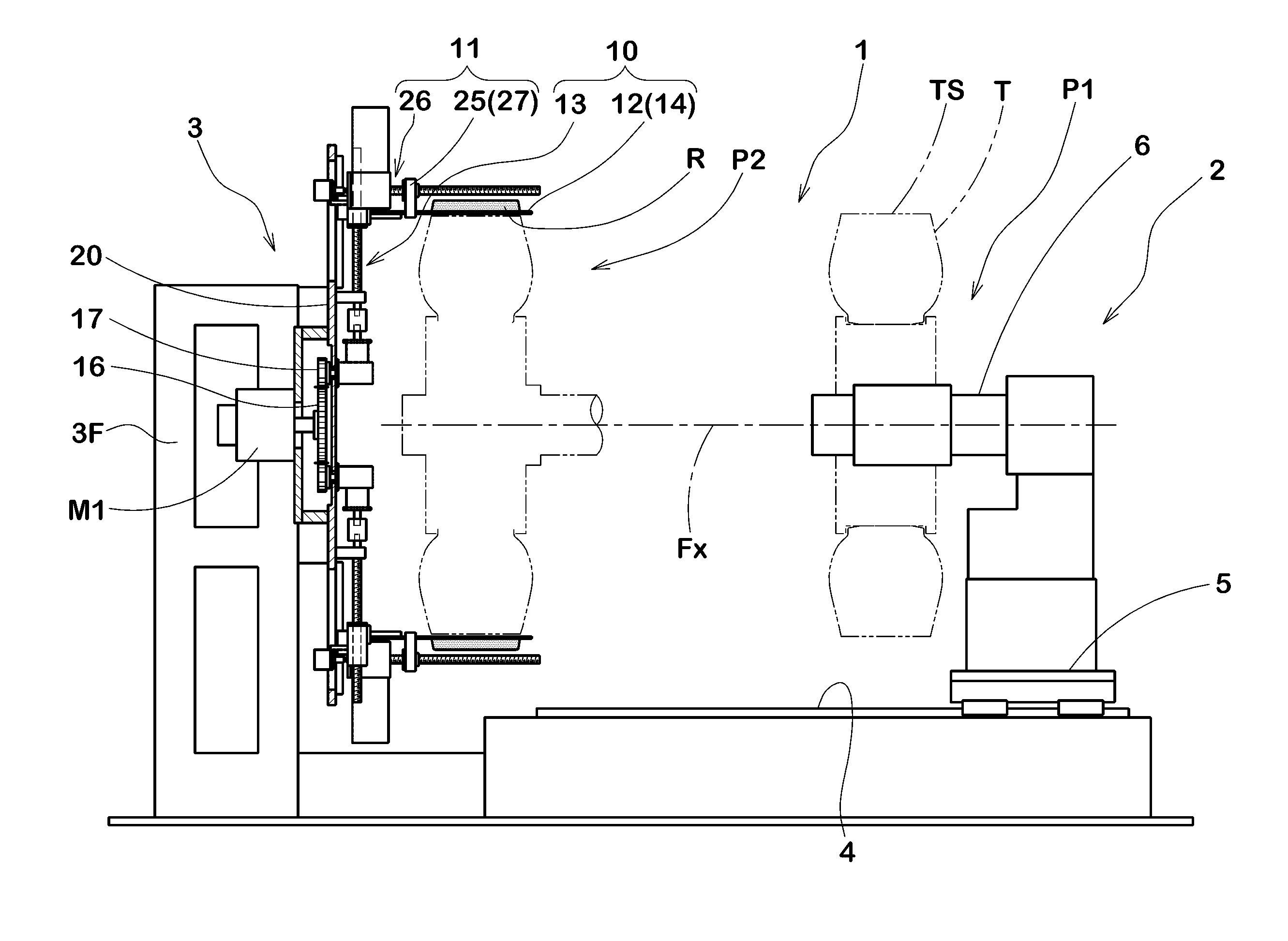
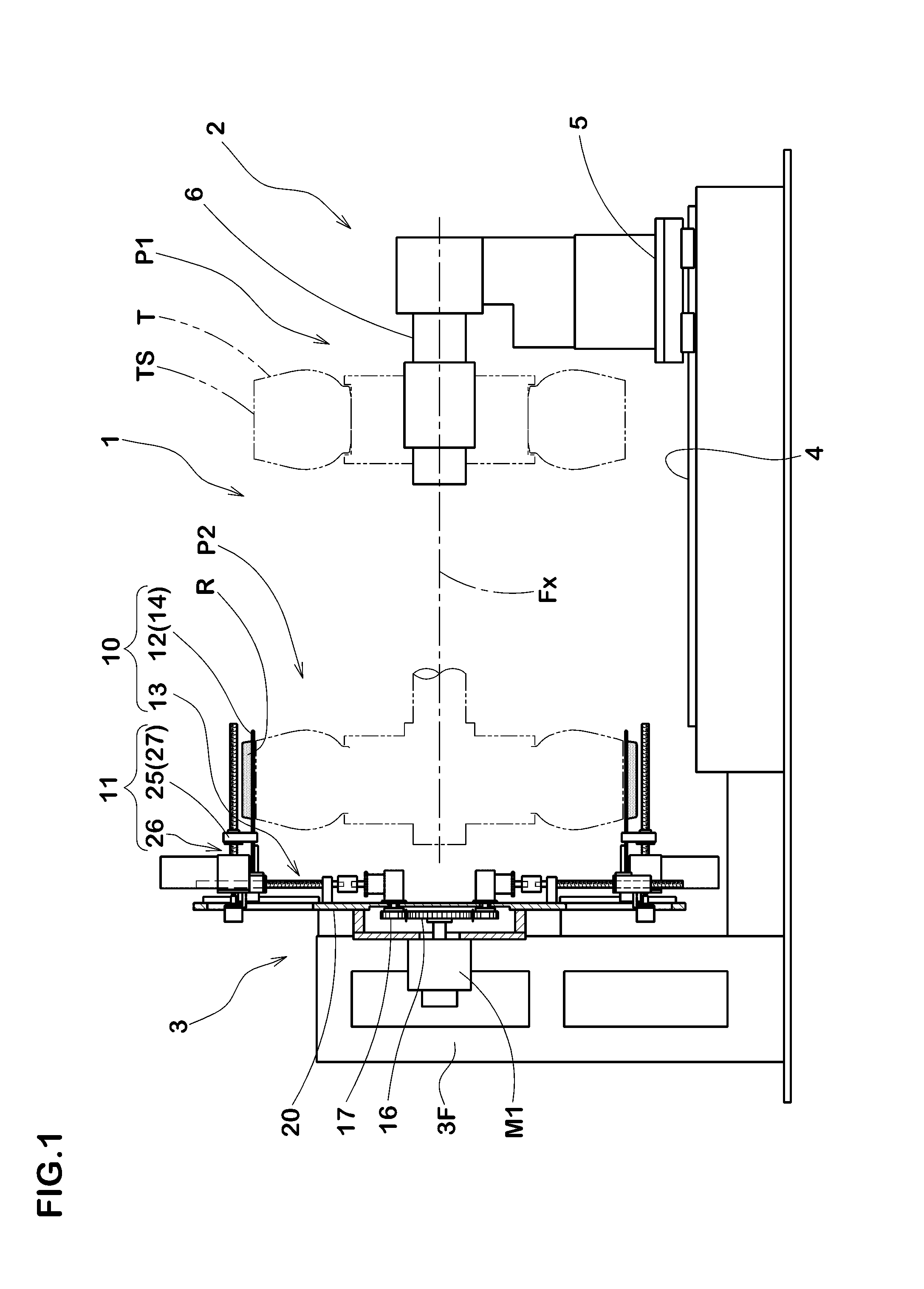
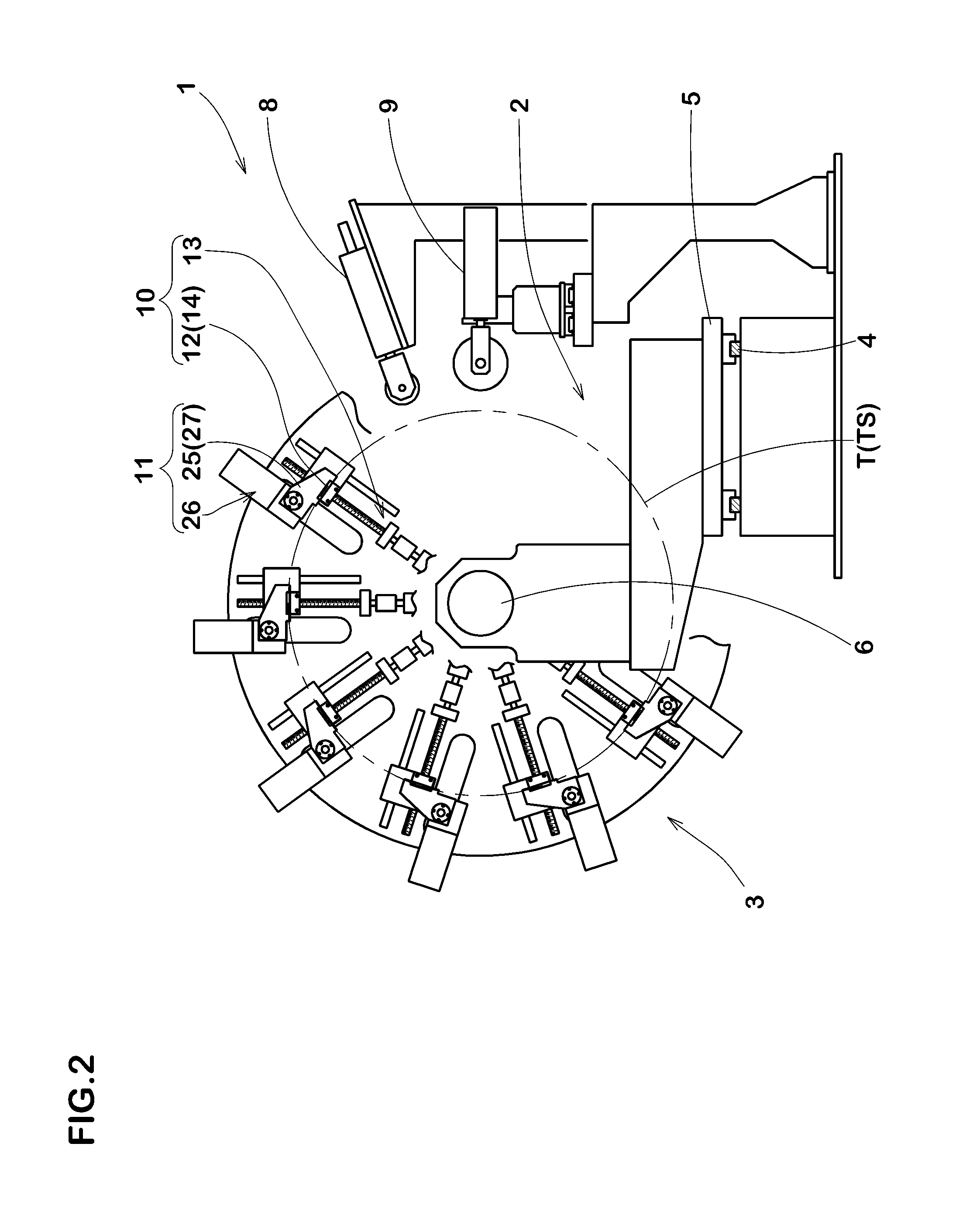
[0043]As shown in FIG. 1 and FIG. 2, the apparatus 1 in this embodiment is for mounting a vulcanized annular tread ring R on an outer peripheral surface TS of a tire base T. The apparatus 1 comprises a tire base holding section 2 and a tread ring mounting section 3.

[0044]The tire base holding section 2 is able to hold the tire base T. The tire base T is held such that the axis direction Fx of the tire becomes horizontal.

[0045]The tire base holding section 2 is movable in the axis direction between a first position P1 on the right and a second position P2 on the left in FIG. 1.

[0046]The tire base holding section 2 in this embodiment is provided with a movable carriage 5 movable on a rail 4 disposed along the axis direction Fx, and a support shaft 6 supported by a main portion provided on the movable carriage 5.

[0047]The tire base T which is mounted on a wheel rim, is held by the support shaf...


PUM

PropertyMeasurementUnit
Diameteraaaaaaaaaa
Speedaaaaaaaaaa

Abstract

An apparatus 1 for mounting an annular tread ring R on an outer peripheral surface TS of a tire base T, which includes a tire base holding section 2 which is movable between a first position P1 and a second position P2 while holding the tire base T, and a tread ring mounting section 3 for mounting the tread ring R on the outer peripheral surface TS of the tire base T. The tread ring mounting section 3 comprises a tread holder 10 for holding the inner circumferential surface of the tread ring R, and a tread pushing-out device 11 for pushing out the tread ring R in the axis direction. At the second position P2, after placing the tread ring R on the outer peripheral surface TS of the tire base T in the tire base holding section 2, the tread ring mounting section 3 pushes out the tread ring R from the tread holder 10 toward the first position P1 by the tread pushing-out device 11. And the tire base holding section 2 moves toward the first position P1 at the same speed as the pushing-out speed of the tread pushing-out device 11. Thereby, the tread ring R is mounted on the outer peripheral surface TS of the tire base T.

Description

TECHNICAL FIELD[0001]The present invention relates to an apparatus for mounting a tread ring on a tire base and a method for manufacturing a retreaded tire, by which an annular tread ring made of vulcanized rubber can be mounted on the outer peripheral surface of the tire base with high accuracy.BACKGROUND ART[0002]In FIG. 8, shown is an example of a precure type tire retreading method. In this method, a tire base (a) is prepared by removing the tread rubber from a spent tire. The tire base (a) has a tread forming face al from which the tread rubber has been removed and which is buffed. To the tread forming face al, an unvulcanized rubber seat b for adhesive purpose is applied.[0003]On the outside of the unvulcanized rubber seat b, a strip-shaped vulcanized tread rubber c is wound.[0004]The tire base (a) around which the tread rubber c has been wound is subjected to a heating treatment.[0005]Thereby, the tire base (a) and the tread rubber c are united (see Patent document 1 for exam...

Claims


Application Information

Patent Timeline
IPC IPC(8): B29D30/56
CPCB29D2030/549B29D30/56
Inventor ISHIHARA, NOBORUONIMATSU, HIROYUKI
Owner SUMITOMO RUBBER IND LTD
Learn More