
System and method for geophysical surveying using electromagnetic fields and gradients

Inactive Publication Date: 2015-06-04
CGG SERVICES SA
View PDF1 Cites 4 Cited by
  • Summary
  • Abstract
  • Description
  • Claims
  • Application Information

AI Technical Summary

Benefits of technology

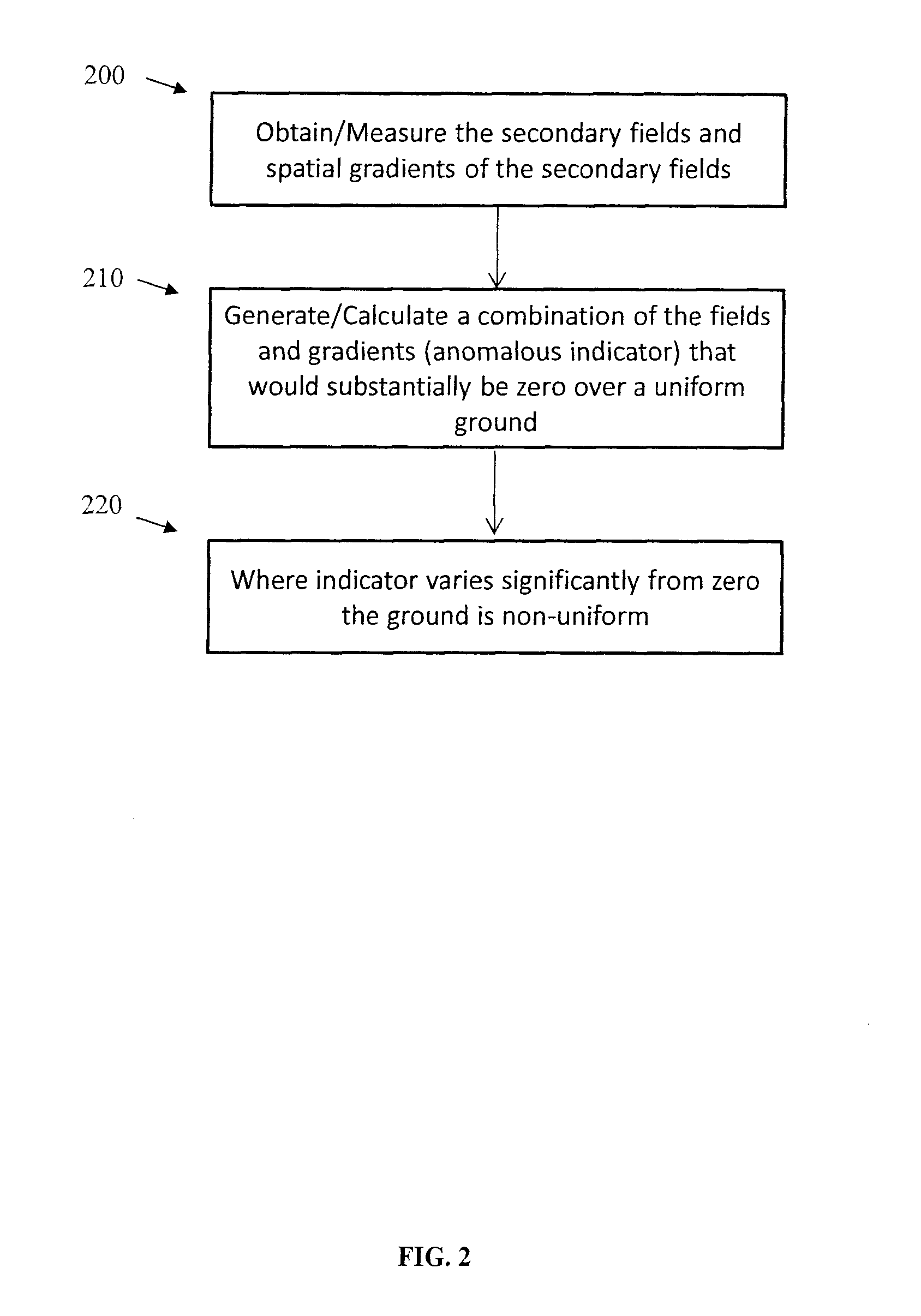
The present invention provides systems and methods for improving the resolution of underground targets using electromagnetic fields and gradients. This is achieved by combining at least one electromagnetic field gradient with the electromagnetic field measurements, which enhances the target's measurements and suppresses those of the background material. The invention also involves identifying a combination of field gradients that will suppress or be null to large scale spatially slowly varying responses and enhance localized responses. This improves the identification of the underground target while maintaining the in-phase response of the localized responses. Additionally, the invention involves measuring the second field and combining it with the estimated second field to improve the signal-to-noise ratio.

Problems solved by technology

Currently, existing EM systems have had limitations when used to identify conductive targets that are embedded in a conductive background material.
In such cases, the response associated with the background material can be significantly greater than the response of the targets, making it difficult to recognize or characterize the targets in a meaningful manner.
In addition, undesirable responses in the forms of various sources of noise, such as noise caused by geological features, noise generated by external EM sources, or noise internally generated in the EM system, may mask anomalous responses that are associated with valuable targets.
This system, however, is limited to frequency domain applications and is quite complicated as it in effect constitutes multiple transmitter / receiver coil-pair systems operating in parallel.
The suggested approach, however, only attempts to correct for direct coupling between the transmitter loop and the receiver coil and is not directed to removing background geological noise.
None of the above prior art systems, however, concerns the measurement of the spatial gradients for EM systems and the related signal analysis for the purpose of identifying anomalous features in a background material.

Method used


Image

  • System and method for geophysical surveying using electromagnetic fields and gradients
  • System and method for geophysical surveying using electromagnetic fields and gradients
  • System and method for geophysical surveying using electromagnetic fields and gradients

Examples


Embodiment Construction

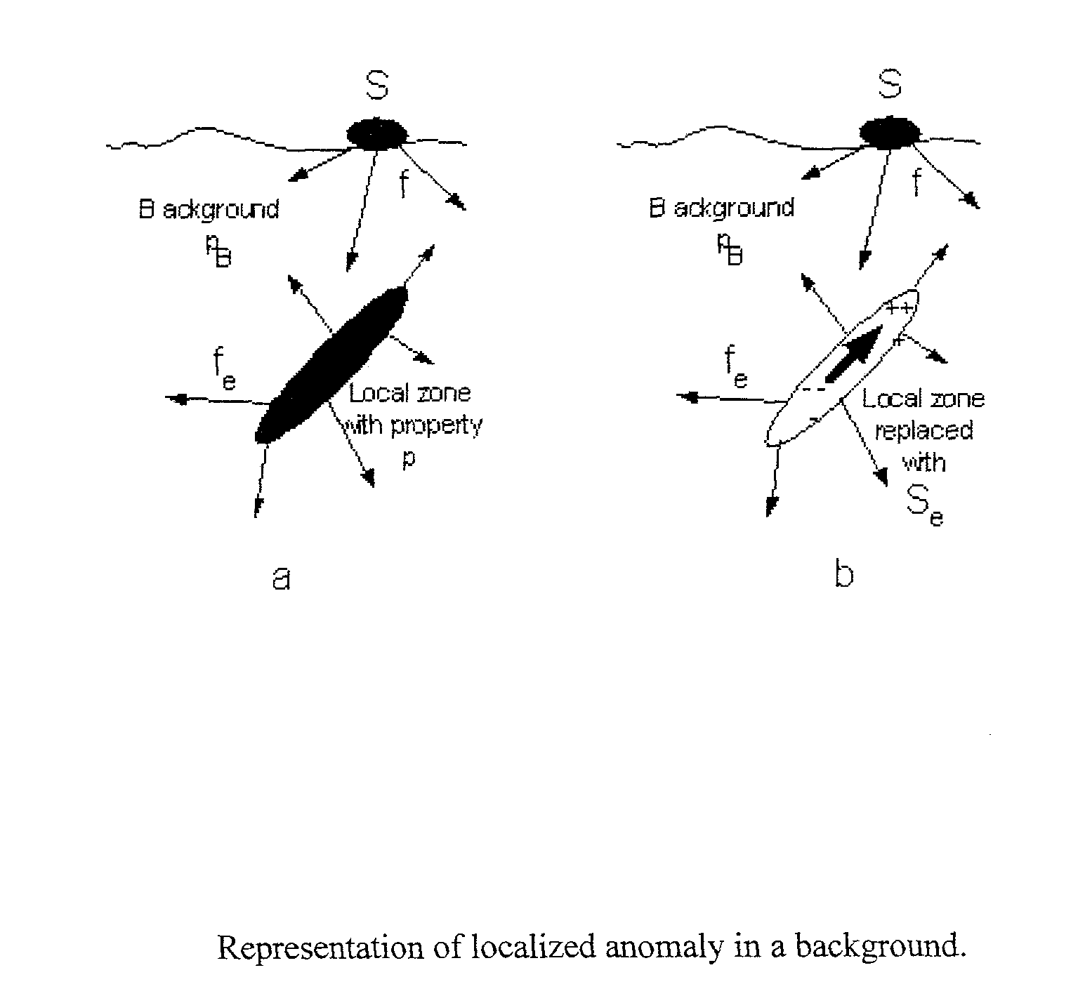
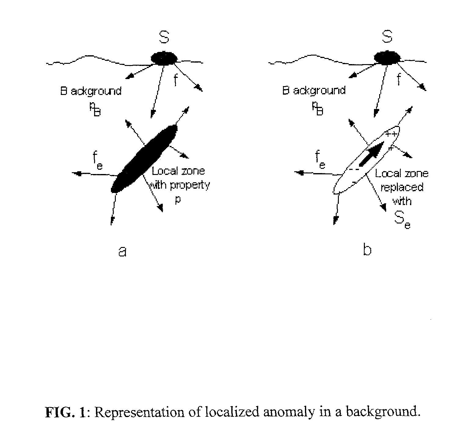
[0031]The purpose of exploration survey measurements is in general to identify localized zones of material with differing physical properties and which have economic significance. Such zones are generally embedded in the background earth material which has more spatially uniform electrical and magnetic (electromagnetic) properties. Any spatial variation in the electromagnetic properties is assumed to vary most strongly as a function of increasing depth and more weakly in the lateral direction. Since both the localized target zones and the background create differing measurable EM responses, techniques that preferentially enhance the localized response and suppress the background response are of great benefit to the geophysical exploration process.

[0032]The present disclosure describes the use of spatial gradients of the fields to create a filtering process that enhances the responses of the localized anomalous features and suppresses the responses of the background.

[0033]The present...


PUM


Abstract

Electromagnetic exploration methods are used to identify a subsurface anomalous feature. This is sometimes difficult in the presence of large fields from the transmitter or other surrounding material that may be above and around the subsurface feature. By constructing linear combinations of the field and gradients of the field it is possible to remove the large fields associated with the transmitter and the surrounding material to make identification of the anomalous subsurface material easier. The fields and gradients can also be combined so as to provide estimates of other electromagnetic field quantities that would be otherwise difficult to measure, for example the electric field or the time derivative of the electric field.

Description

FIELD OF THE INVENTION[0001]The present invention relates to geological surveying, and more particularly, to systems and methods for conducting geophysical surveys using electromagnetic fields and gradients.BACKGROUND OF THE INVENTION[0002]Electromagnetic (EM) measurement systems for geophysical measurement purposes, generally detect the electric and magnetic fields that can be measured in, on or above the earth, in order to identify subsurface changes in electrical properties of materials beneath the earth's surface. Airborne EM systems carry out the field measurements in the air above the earth. A primary goal is to make measurements at a number of spatial locations to identify the size and position of localized material property changes. Such changes can be attributed to a desired outcome such as identifying a localized mineral deposit, a buried object, or the presence or absence of water. The measurements can be made at a range of excitation frequencies (frequency domain) or at ...

Claims


Application Information

Patent Timeline
IPC IPC(8): G01V3/38G01V3/165
CPCG01V3/165G01V3/38G01V3/12
Inventor SMITH, RICHARD STUARTANNAN, ALEXANDER PETER
Owner CGG SERVICES SA
Learn More