Device for generating a virtual light image

Inactive Publication Date: 2015-06-04
NIKITIN IGOR +2
View PDF1 Cites 32 Cited by
  • Summary
  • Abstract
  • Description
  • Claims
  • Application Information

AI Technical Summary

Benefits of technology

[0042]According to one embodiment of this invention, the device according to this invention includes an object that is arranged so that it is visible together with the virtual light image from an observation position. The object can be an arbitrarily shaped item. It can be situated in the vicinity of or near the virtual light image, between the semi-transparent mirror and the virtual light image, or also between the semi-transparent mirror and the retroreflector. A suitable placement of the object is any placement that enables a visual cooperation of the object and the virtual light image. It is thus possible to display a so-called augmented reality. In this case, a real object is superimposed by a light effect that appears to be encompassing it in space.
[0043]To further intensify the vi

Problems solved by technology

This embodiment has the disadvantage that the virtual light image is overlapped by the light of the real light source when an observer looks into the device from the front.
This embodiment in turn has the disadvantage of a poor light output, which results in a low intensity of the virtual light image.
The flat shape and the positioning of the retroreflector surface disclosed in the above-mentioned references have disadvantages that are primarily due to

Method used


Image

  • Device for generating a virtual light image
  • Device for generating a virtual light image
  • Device for generating a virtual light image

Examples


Embodiment Construction

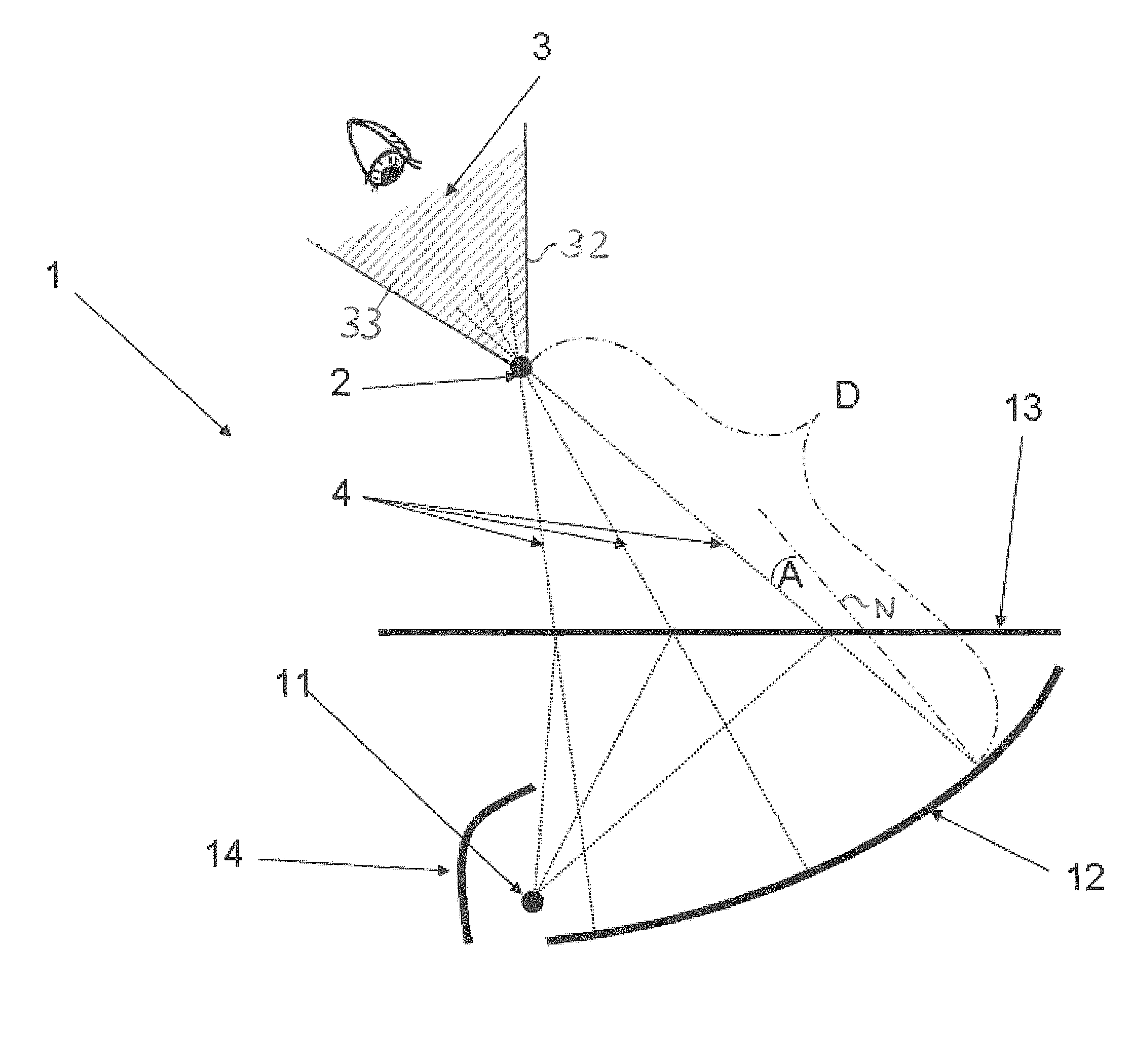
[0053]In particular, FIG. 1 is a schematic depiction of the arrangement of an exemplary embodiment of a device according to this invention 1. The schematic depiction is provided to permit an explanation of how the device 1 works. The device 1 includes a real light source 11, a retroreflector surface 12, and a semi-transparent mirror 13. The light path of a portion of the light emitted by the real light source 11 is schematically represented by the beam paths or light beams 4 in the form of dotted lines 4. The light emitted by the real light source 11 in the direction of the semi-transparent mirror 13 is then partially reflected by the mirror 13. From there, the beams 4 travel to the retroreflector surface 12. The retroreflector surface 12 reflects the beams 4 in the opposite direction, back to the semi-transparent mirror 13. The mirror allows a portion of these beams to pass through. The beams 4 that have been allowed to pass through and intersect at a point and thus establish the l...


PUM

PropertyMeasurementUnit
Angleaaaaaaaaaa
Angleaaaaaaaaaa
Transparencyaaaaaaaaaa

Abstract

A device for generating a virtual light image. The device includes a real light source, a curved retroreflector surface, and a semi-transparent mirror. The retroreflector surface is situated so that the light of the real light source transmitted through the semi-transparent mirror does not reach the retroreflector surface. A shape of the retroreflector surface for a given visibility range, at least in a subregion of the area that is essential for the image in the visibility range, is determined by the fact that at each point of the subregion, the pair of a reflection angle A and an optical distance between this point of the subregion of the retroreflector surface and the virtual light image is Pareto-minimal, provided that the subregion of the retroreflector surface does not interrupt primary beams from the real light source to the semi-transparent mirror.

Description

BACKGROUND OF THE INVENTION[0001]1. Field of the Invention[0002]This invention relates to a device for generating a virtual light image and includes a real light source, a retroreflector surface, and a semi-transparent mirror. The virtual light image of the real light source is produced in that light beams coming from the real light source are reflected on the surface of the semi-transparent mirror, then strike the surface of the retroreflector surface, and from there, through retroreflection, travel back to the semi-transparent mirror. The semi-transparent mirror allows a portion of these beams to pass through. The beams that the semi-transparent mirror allows to pass through then intersect essentially at a point. In this way, a suitably positioned observer perceives a (virtual) light source that appears to be positioned at this intersecting point.[0003]2. Discussion of Related Art[0004]Devices known from the prior art can implement the above-described concept.[0005]PCT Internation...

Claims


Application Information

Patent Timeline
IPC IPC(8): G02B27/14G02B5/12
CPCG02B5/12G02B27/144G02B30/56
Inventor NIKITIN, IGORGOBEL, MARTINHEISENBERG, GERNOT
Owner NIKITIN IGOR
Why Eureka
Try Eureka