
Wireless Full-Duplex System and Method with Self-Interference Sampling

a full-duplex, wireless technology, applied in the direction of link quality based transmission modification, transmission, electrical equipment, etc., can solve the problems of limited communication rate, difficult implementation, and inability to transmit and receive concurrently over the entire frequency band, so as to facilitate wireless networking and facilitate detection

Active Publication Date: 2015-06-04
KHANDANI AMIR KEYVAN
View PDF2 Cites 84 Cited by
  • Summary
  • Abstract
  • Description
  • Claims
  • Application Information

AI Technical Summary

Benefits of technology

The patent describes a technology called full-duplex that allows wireless networks to handle asynchronous users by using a half-duplex, low bit rate, low power, easy to detect network for control signaling. This control network is superimposed on top of the full-duplex data links and uses time multiplexing and carrier sense multiple access (CSMA) to avoid conventional problems of CSMA. The technology also facilitates multi-node distributed and collaborative signaling, improves point-to-point throughput, and enables ultra-low power transmission.

Problems solved by technology

These alternatives have their pros and cons, but both suffer from lack of ability to transmit and to receive concurrently over entire frequency band.
Although full-duplex wireless is theoretically possible, its implementation is difficult due to an excessive amount of interference caused by a transmitter to its own receiver(s).
The impact of full-duplex links in these earlier applications is limited to doubling the communications rate by providing two symmetrical pipes of data flowing in opposite directions.

Method used


Image

  • Wireless Full-Duplex System and Method with Self-Interference Sampling
  • Wireless Full-Duplex System and Method with Self-Interference Sampling
  • Wireless Full-Duplex System and Method with Self-Interference Sampling

Examples


Embodiment Construction

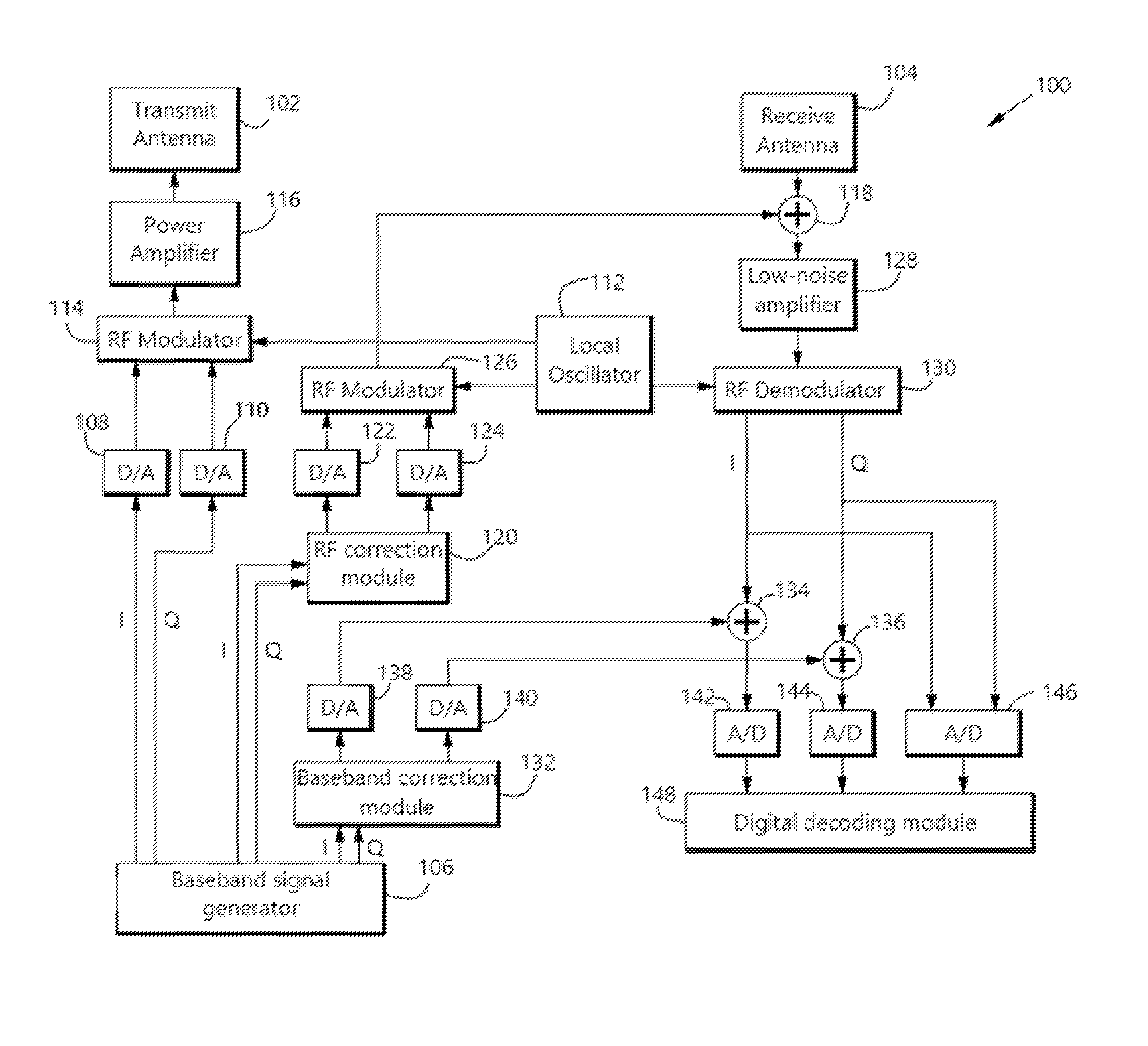
[0022]The present disclosure describes systems and methods performed in a full-duplex transceiver.

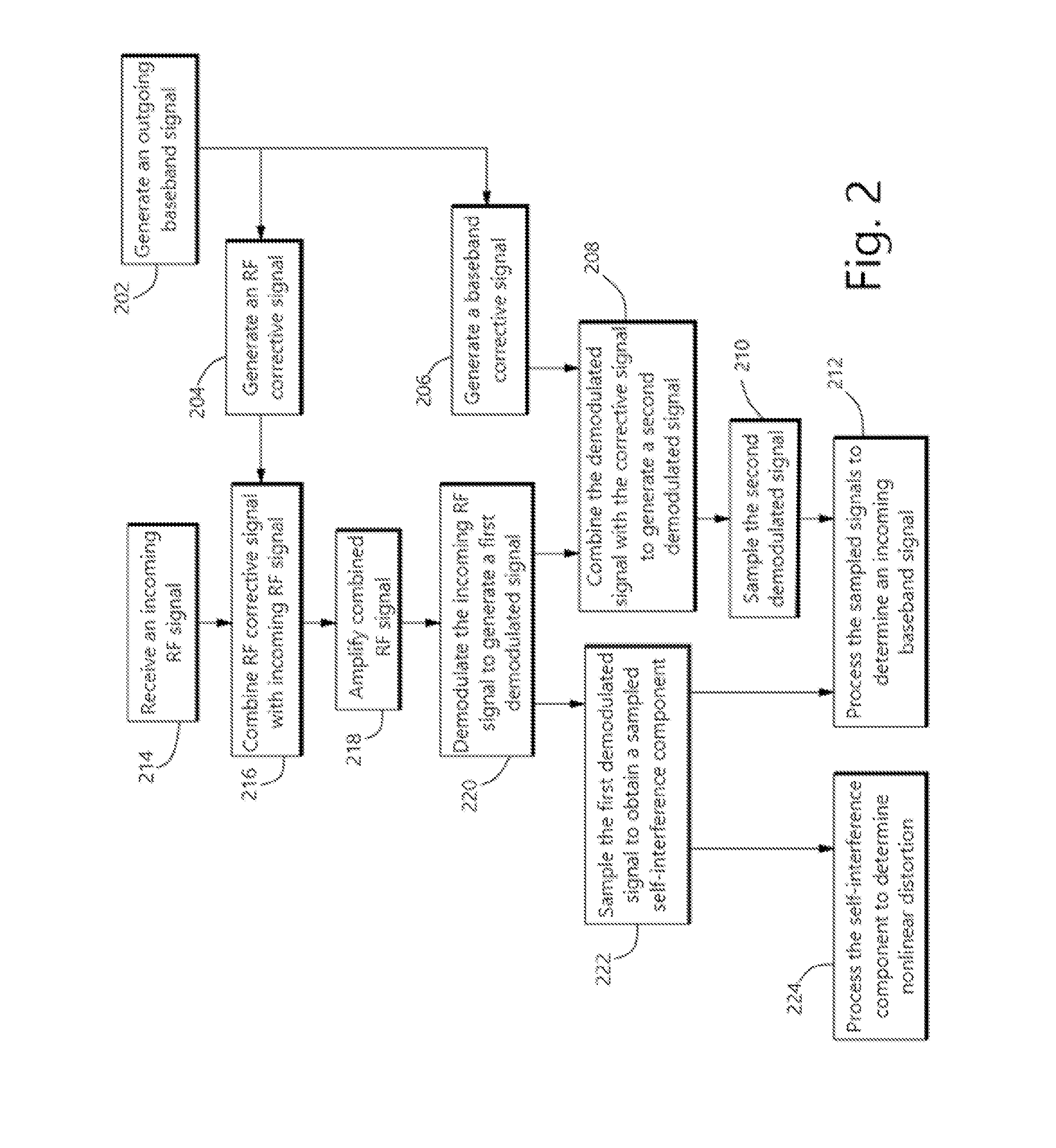
[0023]In one such method, the transceiver receives an incoming radio-frequency signal that includes both a desired radio-frequency signal component and a self-interference component caused by the transceiver's own radio-frequency transmission. The transceiver demodulates the incoming radio-frequency signal to generate a first demodulated signal. The transceiver also generates a first analog corrective signal and combines the first analog corrective signal with the first demodulated signal to generate a second demodulated signal with reduced self-interference. The transceiver samples the first demodulated signal to obtain a sampled self-interference component; and the transceiver processes at least the second demodulated signal and the sampled self-interference component to determine a desired incoming baseband signal. The transceiver may also generate a second analog corrective signal a...


PUM


Abstract

A full-duplex transceiver is provided with componentry and methods for cancellation of nonlinear self-interference signals. The transceiver is capable of receiving an incoming radio-frequency signal that includes both a desired radio-frequency signal component and a self-interference component caused by the transceiver's own radio-frequency transmission. The transceiver demodulates the incoming radio-frequency signal to generate a first demodulated signal. The transceiver combines an analog corrective signal with the first demodulated signal to generate a second demodulated signal with reduced self-interference. The transceiver processes the first and second demodulated signals to determine a desired incoming baseband signal and to determine nonlinear components of the self-interference signal, such as nonlinearities introduced by the transceiver's power amplifier.

Description

CROSS-REFERENCE TO RELATED APPLICATIONS[0001]The present application is a non-provisional filing of, and claims benefit under 35 U.S.C. §119(e) from the following applications: U.S. Provisional Patent Application Ser. No. 61 / 910,332, filed Nov. 30, 2013, U.S. Provisional Patent Application Ser. No. 61 / 916,511, filed Dec. 16, 2013, both of which are incorporated herein by reference in their entirety.FIELD[0002]The present disclosure relates to wireless communications. In particular, the present disclosure relates to systems and methods to establish two-way (full-duplex) wireless links.BACKGROUND[0003]A communication link with capability to support connections in both transmit and receive directions at the same time and over the entire frequency band is called full-duplex, or two-way. In contrast, a link that can support connection in only one direction at a time (over a given frequency band) is called one-way or half-duplex. Current wireless systems are one-way and rely on either sep...

Claims


Application Information

Patent Timeline
IPC IPC(8): H04L5/14H04L1/00
CPCH04L1/0031H04L5/143H04B1/525
Inventor KHANDANI, AMIR KEYVAN
Owner KHANDANI AMIR KEYVAN
Learn More