Packet Data Network Gateway and Terminal Mobility Management System

a packet data network and terminal technology, applied in the field of packet data network gateway and terminal mobility management system, can solve the problems of series of problems, wasting the transmission bearer resources of operators, and the problem of circuitous routing becoming more apparent, so as to reduce the transmission delay of data packets, eliminate circuitous routing, and save transmission bearer resources

Inactive Publication Date: 2015-06-04
ZTE CORP
View PDF5 Cites 36 Cited by
  • Summary
  • Abstract
  • Description
  • Claims
  • Application Information

AI Technical Summary

Benefits of technology

[0032]The embodiment of the present invention re-selects a P-GW to which the UE is attached, so as to eliminate the circuitous routing in the process of the UE connecting and using a service, save transmission bearer resources, reduce transmission delay of data packet, and ensure that after the attached P-GW changes, the UE is still reachable, and the UE and its peer end cannot have a perception in the IP level that the UE moves.

Problems solved by technology

Such unchanged anchor point will trigger a series of problems.
For example, it might lead to the circuitous routing problem widely recognized in the industry, that is: in a process of one connection as well as a process of the UE using service, the location of UE might change, and when the current location of UE is leaving away from its anchor point, the data flow that the UE interacts with the outside also needs to be forwarded by its anchor point, particularly when the current location of UE is relatively close to the service source that the UE accesses, the circuitous routing problem becomes more apparent (FIG. 2b).
The circuitous routing brings problems in the following aspects:
(One) wasting the transmission bearer resources of operators, which is not conducive to cost savings;
(Two) increasing the delay of transmitting and receiving IP packets between the UE and its communicating peer end, which is not conducive to improving the user's service experience;
(Three) increasing the likelihood of network congestion when the UE's IP packets are transmitted over the network, resulting in that the UE services, for example real-time services such as voice and video, are hindered or even impossible to be implemented.

Method used


Image

  • Packet Data Network Gateway and Terminal Mobility Management System
  • Packet Data Network Gateway and Terminal Mobility Management System
  • Packet Data Network Gateway and Terminal Mobility Management System

Examples


first embodiment

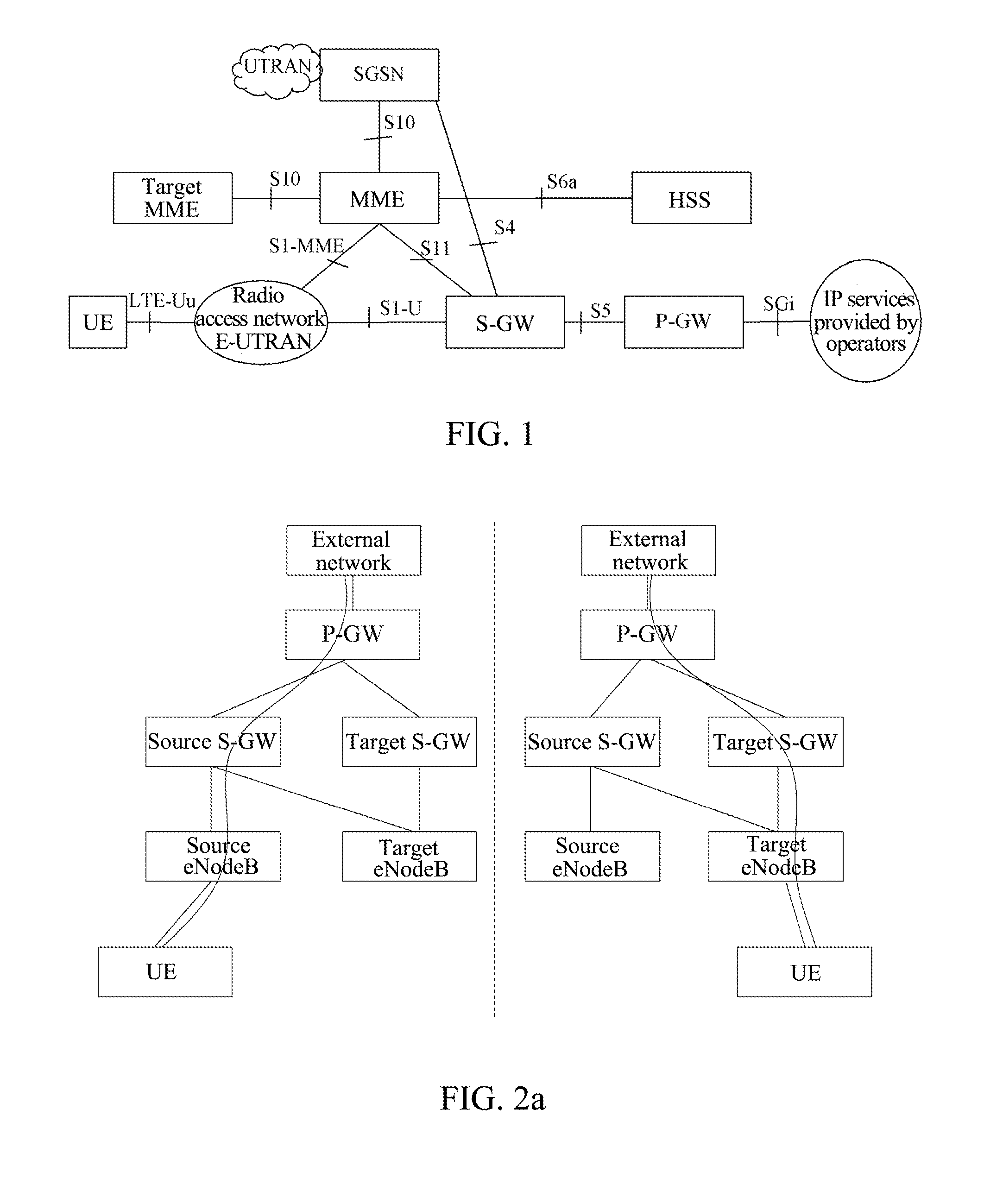
[0057]The first embodiment shown in FIG. 3 is an example of changing the P-GW to which the UE is currently attached in the S1 handover scenario. It should be noted that the eNodeB to which the UE is attached before the handover is “Source eNodeB”, and the S-GW attached before the handover is “Source S-GW”; the eNodeB attached after the handover is “Target eNodeB”, and the S-GW attached after the handover is “Target S-GW”. Moreover, in a handover scenario, the UE may change the MME that is currently in use, accordingly, the MMEs used before and after the handover are called “source MME” and “target MME” respectively. The P-GW to which the UE is attached is changed in the handover in the present embodiment, and the P-GWs before and after the handover are called “source P-GW” and “target P-GW” respectively. Before performing the S1 handover, the uplink and downlink data transmission path of UE is: UE Source eNodeB Source S-GW Source P-GW. The specific steps of the present embodiment...

second embodiment

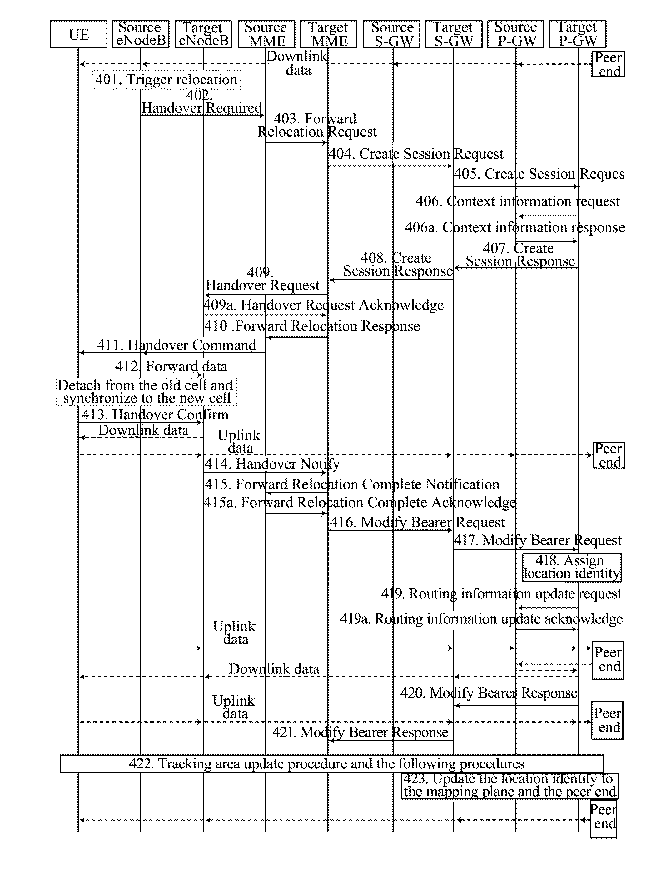
[0112]FIG. 4 shows the second embodiment of the present invention, and it is an example of changing the P-GW to which the UE is currently attached in the S1 handover scenario. It specifically comprises the following steps:

[0113]steps 401-403: the same as steps 301-303;

[0114]step 404: the target MME selects a target S-GW for the UE, sends a create session request message to the target S-GW, and creates session information for the UE on said S-GW, wherein the create session request message carries the control plane address information of source P-GW, the PDN address and the PDN connection information;

[0115]Preferably, as described in step 312, the target MME may select one new P-GW for UE as the target P-GW, and carries the address information of the P-GW in said create session request message.

[0116]Step 405: the target S-GW sends the target P-GW a create context request message (such as sending the create session request message) carrying the identity of UE (such as the UE's IMSI), s...

third embodiment

[0151]FIG. 5 shows a third embodiment of the present invention, and is also an example of changing the P-GW to which the UE is currently attached in the S1 handover scenario. It specifically comprises the following steps:

[0152]steps 501-512: the same as the steps 301-312;

[0153]step 513: the target S-GW sends a Modify Bearer Request message to the source P-GW;

[0154]The purpose of the message is to update the context information about UE stored in the source P-GW, and it needs to carry the downlink data channel address information assigned by the target S-GW to the UE to be used in the target S-GW, the control plane address information of S-GW, and the address information of the target P-GW.

[0155]It should be noted that, as described in the first two embodiments, the target P-GW may be selected by the target MME for the target S-GW, or selected by the target S-GW itself.

[0156]It also should be noted that, the target P-GW can also be selected by the source P-GW. For example, the source...


PUM


Abstract

A packet data network gateway and a UE mobility management system are disclosed. In the packet data network gateway, a context management unit is configured to: when the P-GW is selected as the UE's target P-GW, create a context for the UE and store the UE's context information from S-GW and a source P-GW to which the UE is currently attached; an identity management unit is configured to: assign a location identity including the UE's routing information to the UE. The present invention reselects a P-GW for the UE to attach, thereby eliminating the circuitous routing in the process of the UE connecting and using services, saving transmission bearer resources, reducing transmission delay of data packet, and ensuring that the UE is still reachable after changing the attached P-GW, thus neither the UE nor the peer end is aware of the movement of the UE in the IP level.

Description

TECHNICAL FIELD[0001]The patent document relates to the evolved packet system in the field of mobile communications, and more particularly, to a packet data network gateway and a UE mobility management system.BACKGROUND OF THE INVENTION[0002]The 3rd Generation Partnership Project (referred to as 3GPP) Evolved Packet System (referred to as EPS) is composed of Evolved Universal Terrestrial Radio Access Network (referred to as E-UTRAN), Mobility Management Entity (referred to as MME), Serving Gateway (S-GW), Packet Data Network Gateway (referred to as P-GW or PDN GW), Home Subscriber Server (referred to as HSS), 3GPP Authentication, Authorization and Accounting (referred to as AAA) server, Policy and Charging Rules Function (referred to as PCRF) entity and other support nodes.[0003]FIG. 1 is a structural diagram of an EPS system in the related art, as shown in FIG. 1, the MME is responsible for control plane related work such as mobility management and non-access stratum signaling proc...

Claims


Application Information

Patent Timeline
Patent Type & Authority Applications(United States)
IPC IPC(8): H04W28/02H04W36/00H04W40/36H04W8/02
CPCH04W28/0226H04W8/02H04W88/16H04W28/0252H04W40/36H04W36/0044H04W36/0033H04W8/18
Inventor LUO, WEN
Owner ZTE CORP
Why Eureka
Try Eureka