
Display Device Having Partial Panels and Driving Method thereof

a technology of partial panels and display devices, applied in the field of display, can solve the problems of insufficient touch sensing frequency of 60 hz, namely, touch sensing of 60 times in one second, etc., and achieve the effect of increasing the frequency of touch sensing or touch report rate, reducing the number of signal lines, and reducing the size of the bezel

Active Publication Date: 2015-06-11
LG DISPLAY CO LTD
View PDF4 Cites 20 Cited by
  • Summary
  • Abstract
  • Description
  • Claims
  • Application Information

AI Technical Summary

Benefits of technology

The patent describes a method to increase the frequency of touch sensing in a display panel by driving multiple panel portions and utilizing a touch-sensing mode period between driving the panels. This method also reduces the number of signal lines needed, which helps to maintain or reduce the size of the bezel.

Problems solved by technology

However, if the user's touch operation becomes fast and a response speed of the touch operation is considered, the touch sensing frequency of 60 Hz (namely, touch-sensing of 60 times in one second) may be insufficient.

Method used


Image

  • Display Device Having Partial Panels and Driving Method thereof
  • Display Device Having Partial Panels and Driving Method thereof
  • Display Device Having Partial Panels and Driving Method thereof

Examples


first embodiment

[0080]FIG. 4 illustrates panel portions and a driving method according to the Part (a) illustrates the display panel divided into two panel portions and the signals applied to each of them and part (b) illustrates the pixel display and the touch sensing method using the panel portions.

[0081]Hereafter, it will be explained that the aforementioned embodiment may have the number of the gate lines equal to 1280, namely N=1280, on the entire display panel, but is not limited thereto.

[0082]The display device according to the first embodiment as shown in FIG. 4 may comprise a first panel portion 410 including a first subset of the gate lines (#1 to #640) and a second panel portion 410 including a second subset of the gate lines (#641 to #1280). The data driver (D-IC) 450 may be arranged at a non-display area on one side of the display panel. Although such data driver 450 may be represented with another explanation, it will be understood that it may include all elements which generate sign...

second embodiment

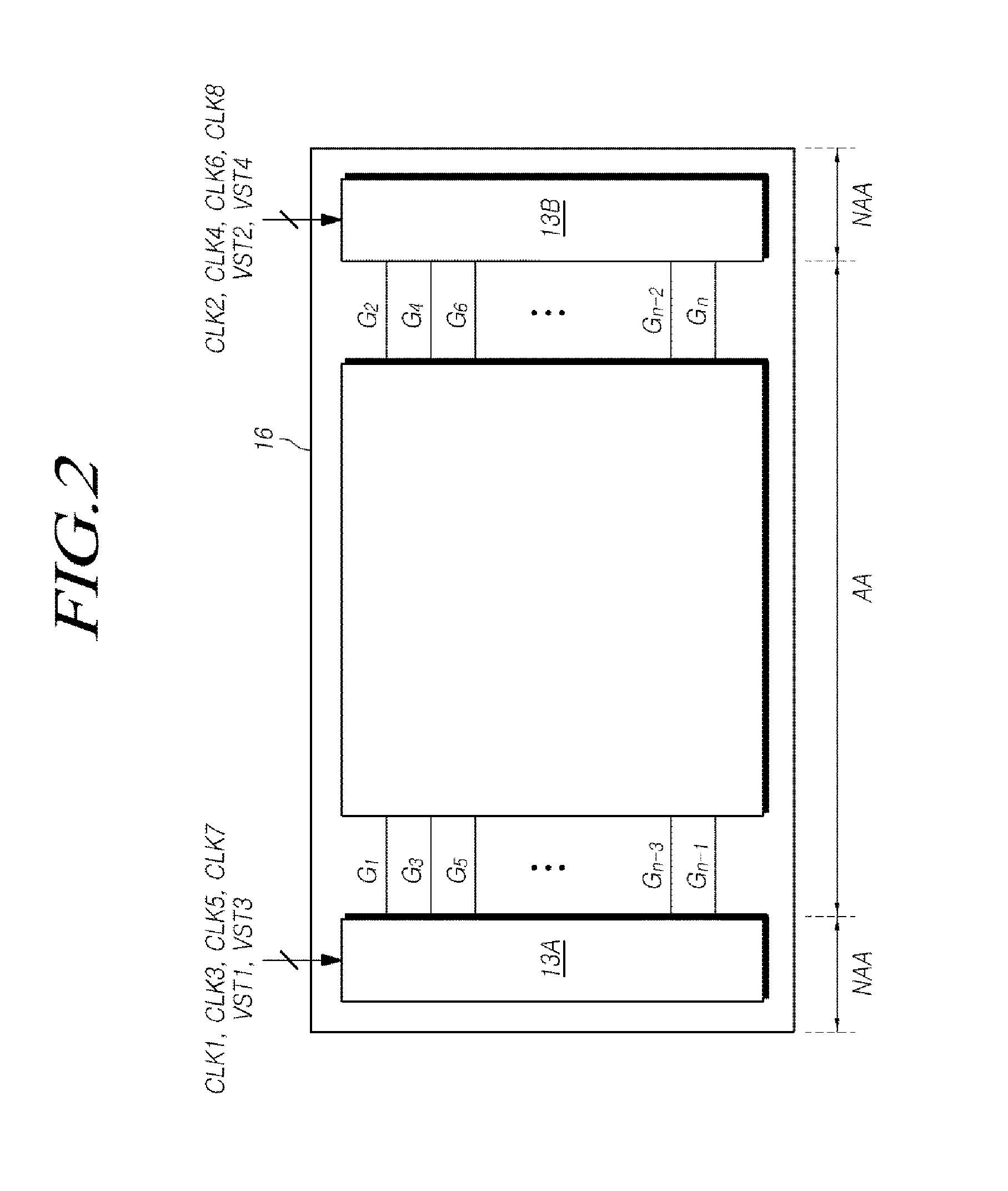
[0123]Referring to FIG. 6a, for the first display mode of the first panel portion in the display device the signals applied to the first gate driver 411 may be four clock signals CLK1 to CLK4 that are 2H 4 phase signals, a first start pulse VST1, a second start pulse VST2 and two end signals END1 and END2. For the second display mode of the second panel portion, the signals applied to the second gate driver 421 may be four clock signals CLK1 to CLK4 that are 2H 4 phase signals, a third start pulse VST3, a fourth start pulse VST4 and two end signals END1 and END2 equal to the end signals used in the first panel portion.

[0124]The display device according to the second embodiment is similar to that according to the first embodiment. A difference is that the first embodiment applies four end signals to the first panel portion, whereas the second embodiment applies only two end signals END1 and END2 to the first panel portion.

[0125]Hereafter, the driving method of the panel portions acc...


PUM


Abstract

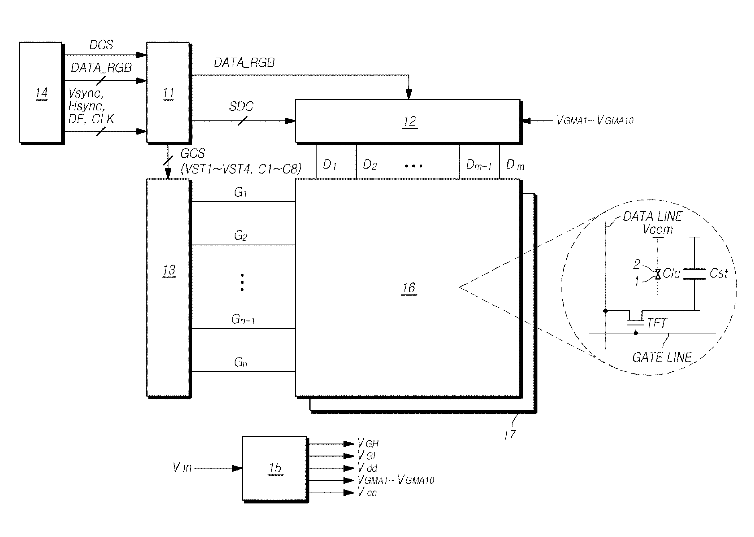
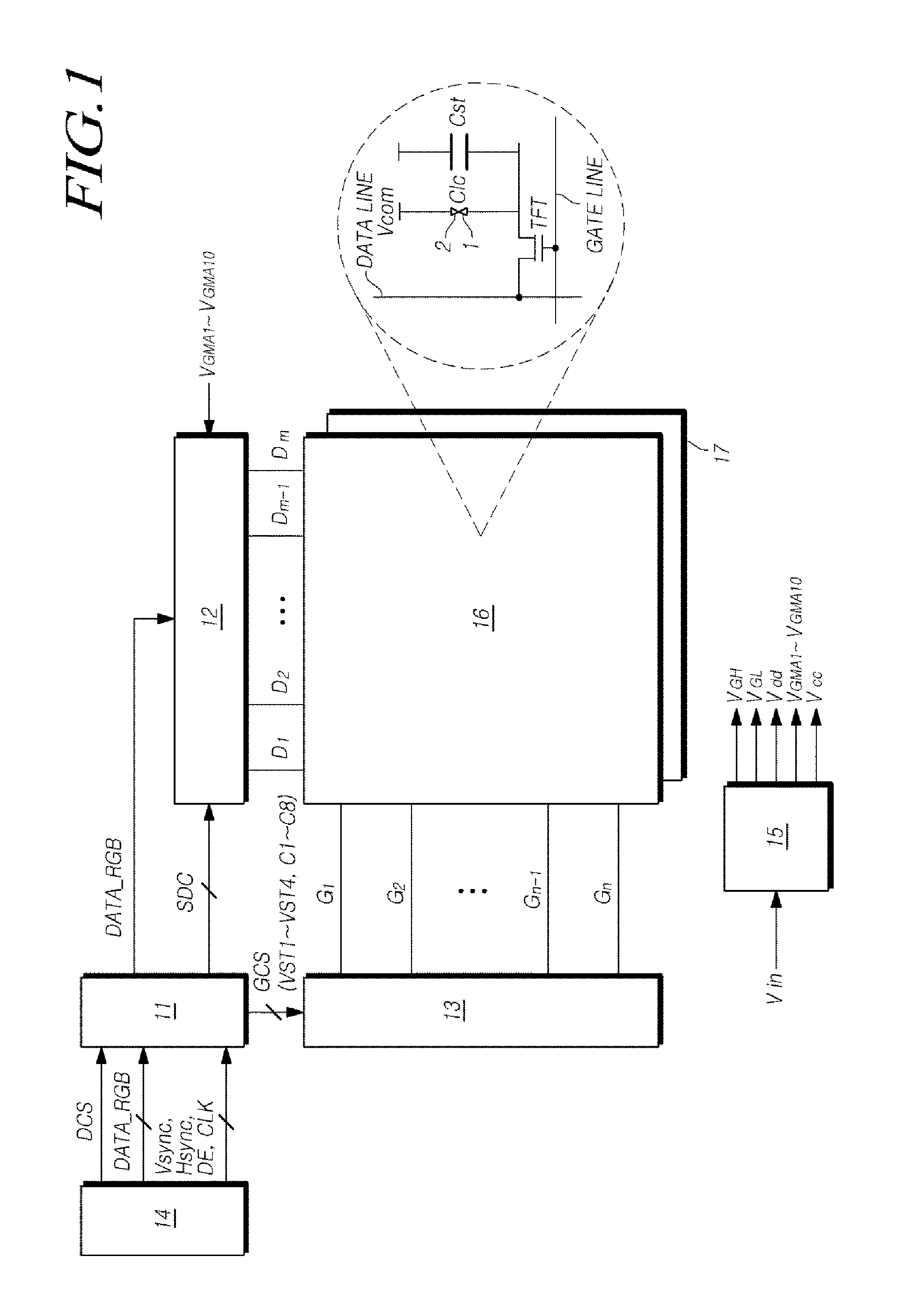
Disclosed are a display device comprising panel portions and a driving method thereof, which are capable of dividing the display panel into two or more panel portions and adding a touch mode between the display modes of each panel portion, thereby improving the frequency of the touch sensing or the touch report rate. The display device comprising panel portions and the driving method thereof can reduce the pulse width of the signals from 4H 8phase to 2H 4phase by using an oxide TFT and maintain or reduce the number of the signal lines applied to the gate driver of the partial display panel, thereby having the advantages in terms of the bezel.

Description

CROSS-REFERENCE TO RELATED APPLICATION[0001]This application claims priority from and the benefit under 35 U.S.C. §119(a) of Korean Patent Application No. 10-2013-0153149, filed on Dec. 10, 2013, which is hereby incorporated by reference for all purposes as if fully set forth herein.BACKGROUND OF THE INVENTION[0002]1. Field of the Invention[0003]The present disclosure relates to a display device comprising a panel divided into different panel portions and a driving method thereof. More specifically, the present disclosure relates to a display device comprising two or more panel portions equipped with touch functions and a driving method thereof.[0004]2. Description of the Prior Art[0005]As information oriented society has been developed, demands for displays for displaying an image are increasing. Thus, various flat displays such as a liquid crystal display (LCD), plasma display panel (PDP), and organic light emitting display (OLED) have been used recently.[0006]The liquid crystal d...

Claims


Application Information

Patent Timeline
Patent Type & Authority Applications(United States)
IPC IPC(8): G06F3/041G09G3/36
CPCG09G2310/0221G09G3/3674G09G3/3696G06F3/0412G09G3/3666G09G2300/0413G09G2310/0224G09G2354/00G06F3/04184G02F1/13338G06F3/0416G06F3/044G06F3/045G06F3/047G06F2203/04101G06F2203/04104G06F2203/04113G09G3/36G09G3/3677G06F3/04166
Inventor PARK, YONGCHANHWANG, SANGSOO
Owner LG DISPLAY CO LTD
Learn More