

User authentication apparatus and method for POS system
a user authentication and user authentication technology, applied in the field of user authentication apparatus and method for a pos system, can solve the problems of financial accidents, difficult to distinguish between a stolen or lost payment card or a payment card used by an unauthorized person,
- Summary
- Abstract
- Description
- Claims
- Application Information
AI Technical Summary
Benefits of technology
Problems solved by technology
Method used
Image

Examples
first embodiment
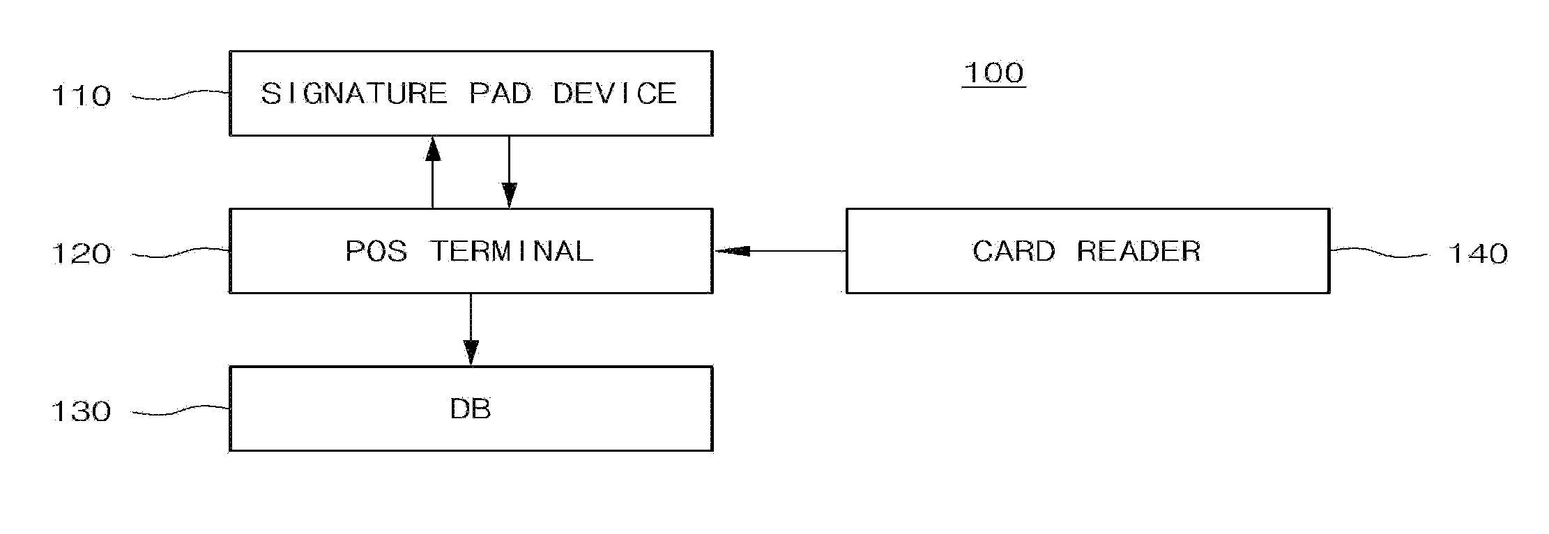
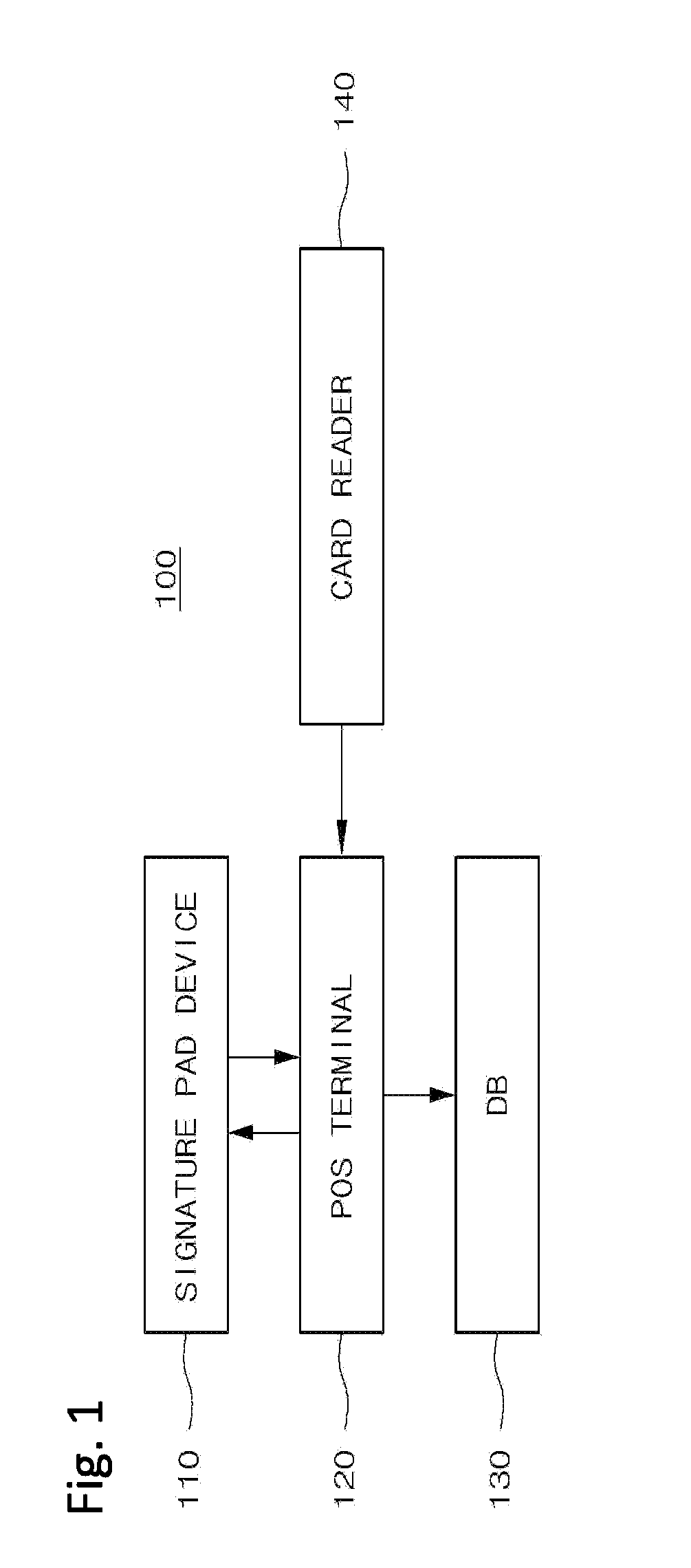
[0032]FIG. 3A is a block diagram of a user authentication apparatus for a POS system in accordance with the present invention. As illustrated in FIG. 3A, the POS system 300 may include a signature pad device 310, a POS terminal 320, and a DB 330.
[0033]The signature pad device 310 may include a signature pad module 311 and a camera module 312. The camera module 312 may include a photographing unit 312A and a transmitting and receiving unit 312B.
[0034]The POS terminal 320 may include a sale management module 321 and a clientele analysis module 322. The clientele analysis module 322 may include a control unit 322A, an analysis processing unit 322B, and a transmitting and receiving unit 322C.
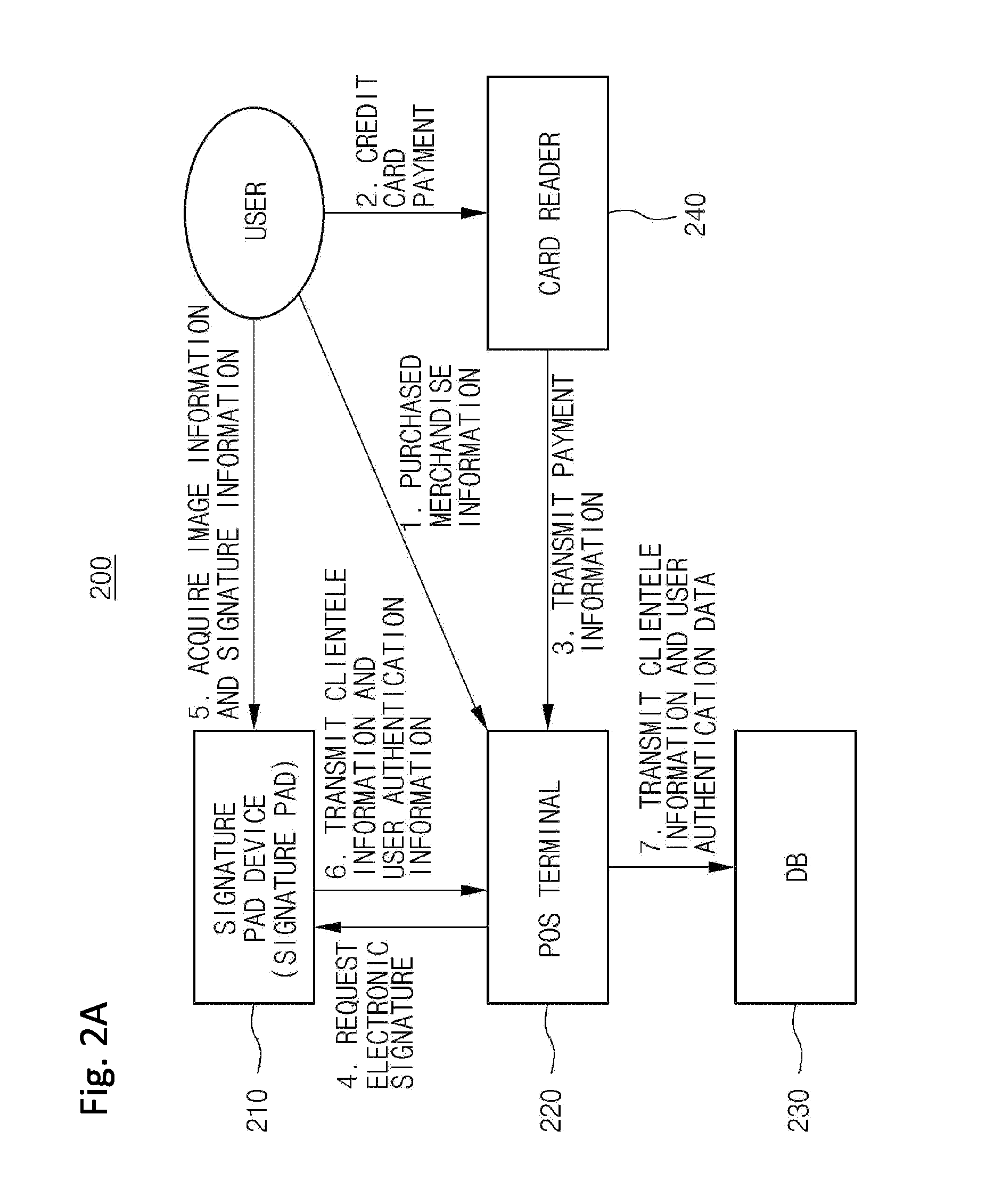
[0035]FIG. 3B is a diagram for explaining the operations of the respective blocks in the user authentication apparatus for the POS system in accordance with the first embodiment of the present invention.
[0036]FIG. 3C is a flowchart illustrating the entire operation of the user authentication apparat...
second embodiment
[0043]FIG. 4A is a block diagram of a user authentication apparatus for a POS system in accordance with the present invention. As illustrated in FIG. 4A, the POS system 400 may include a signature pad device 410, a POS terminal 420, and a DB 430.
[0044]The signature pad device 410 may include a signature pad module 411, a camera module 412, and a clientele analysis module 413. The clientele analysis module 413 may include a control unit 413A, an analysis processing unit 413B, and a transmitting and receiving unit 413C.
[0045]FIG. 4B is a diagram for explaining the operations of the respective blocks in the user authentication apparatus for the POS system in accordance with the second embodiment of the present invention.
[0046]FIG. 4C is a flowchart illustrating the entire operation of the user authentication apparatus for the POS system in accordance with the second embodiment of the present invention.
[0047]Referring to FIGS. 4A to 4C, the second embodiment of the present invention wil...
third embodiment
[0052]FIG. 5 is a block diagram of a user authentication apparatus for a POS system in accordance with the present invention. As illustrated in FIG. 5, the POS system 500 may include a signature pad device 510, a POS terminal 520, and a DB 530.
[0053]The signature pad device 510 may include a camera module 511. The POS terminal 520 may include a sale management module 521 and a clientele analysis module 522.
[0054]The third embodiment of FIG. 5 is different from the second embodiment of FIG. 4B in that the clientele analysis module 522 of the POS terminal 520 performs face recognition and user authentication and transmits the authentication result to the DB 530.
PUM
 Abstract
Description
Claims
Application Information