Encoder, decoder, system and method employing a residual concept for parametric audio object coding

a residual concept and audio object technology, applied in the field of audio signal encoding, decoding and processing, can solve the problems of processing no longer achieving an adequate subjective sound, the residual concept of saoc cannot be used with single- or two-channel signal mixtures, and the inability to perfectly generate the desired target output scen

Active Publication Date: 2015-06-11
FRAUNHOFER GESELLSCHAFT ZUR FOERDERUNG DER ANGEWANDTEN FORSCHUNG EV
View PDF7 Cites 15 Cited by
  • Summary
  • Abstract
  • Description
  • Claims
  • Application Information

AI Technical Summary

Benefits of technology

[0041]According to a further embodiment, the decoder may be adapted to not determine Channel Prediction Coefficients to determine the plurality of second estimated audio object signals. Embodiments provide concepts so that the calculation of the Channel Prediction Coefficients that have so far been necessitated for decoding in state-of-the-art SAOC, is no longer necessitated for decoding.

Problems solved by technology

Due to the underlying limitations of the parametric estimation of the audio objects at the decoding side; in most cases, the desired target output scene cannot be perfectly generated.
At extreme operating points (for example, solo playback of one audio object), often, the processing can no longer achieve an adequate subjective sound.
The SAOC residual concept can only be used with single- or two-channel signal mixtures due to the limitations of the TTN-box.
Furthermore, due to the corresponding computational complexity of their estimation, the SAOC EAO processing sets limitations on the number of EAOs (i.e., up to 4).
Because of these limitations, the SAOC EAO residual handling concept cannot be applied to multi-channel (e.g., 5.1) downmix signals or used for more than 4 EAOs.

Method used


Image

  • Encoder, decoder, system and method employing a residual concept for parametric audio object coding
  • Encoder, decoder, system and method employing a residual concept for parametric audio object coding
  • Encoder, decoder, system and method employing a residual concept for parametric audio object coding

Examples


Embodiment Construction

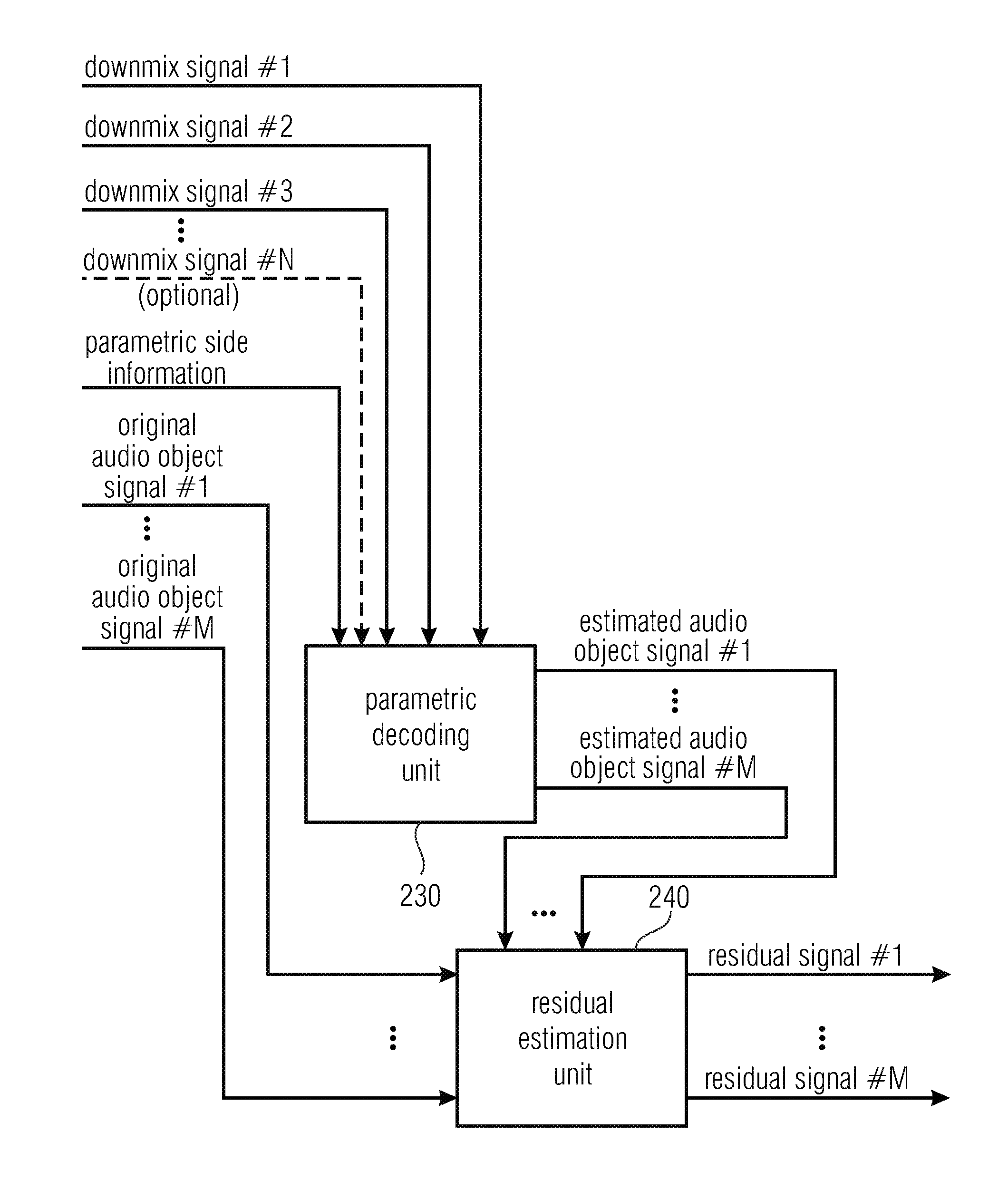
[0080]FIG. 2a illustrates a residual signal generator 200 according to an embodiment.

[0081]The residual signal generator 200 comprises a parametric decoding unit 230 for generating a plurality of estimated audio object signals (Estimated Audio Object Signal #1, . . . Estimated Audio Object Signal #M) by upmixing three or more downmix signals (Downmix Signal #1, Downmix Signal #2, Downmix Signal #3, . . . , Downmix Signal #N). The three or more downmix signals (Downmix Signal #1, Downmix Signal #2, Downmix Signal #3, . . . , Downmix Signal #N) encode a plurality of original audio object signals (Original Audio Object Signal #1, . . . , Original Audio Object Signal #M). The parametric decoding unit 230 is configured to upmix the three or more downmix signals (Downmix Signal #1, Downmix Signal #2, Downmix Signal #3, . . . , Downmix Signal #N) depending on parametric side information indicating information on the plurality of original audio object signals (Original Audio Object Signal #...


PUM


Abstract

A decoder is provided. The decoder includes a parametric decoding unit for generating a plurality of first estimated audio object signals by upmixing three or more downmix signals, wherein the three or more downmix signals encode a plurality of original audio object signals, wherein the parametric decoding unit is configured to upmix the three or more downmix signals depending on parametric side information indicating information on the plurality of original audio object signals. Moreover, the decoder includes a residual processing unit for generating a plurality of second estimated audio object signals by modifying one or more of the first estimated audio object signals, wherein the residual processing unit is configured to modify the one or more of the first estimated audio object signals depending on one or more residual signals.

Description

CROSS-REFERENCE TO RELATED APPLICATIONS[0001]This application is a continuation of copending International Application No. PCT / EP2013 / 057932, filed Apr. 16, 2013, which claims priority from U.S. Provisional Application No. 61 / 681,730, filed Aug. 10, 2012, each of which is incorporated herein in its entirety by this reference thereto.BACKGROUND OF THE INVENTION[0002]The present invention relates to audio signal encoding, decoding and processing, and, in particular, to an encoder, a decoder and a method, which employ residual concepts for parametric audio object coding.[0003]Recently, parametric techniques for the bitrate-efficient transmission / storage of audio scenes comprising multiple audio objects have been proposed in the field of audio coding (see, e.g., [BCC], [JSC], [SAOC], [SAOC1] and [SAOC2]) and informed source separation (see, e.g., [ISS1], [ISS2], [ISS3], [ISS4], [ISS5] and [ISS6]). These techniques aim at reconstructing a desired output audio scene or a desired audio sou...

Claims


Application Information

Patent Timeline
Patent Type & Authority Applications(United States)
IPC IPC(8): G10L19/008
CPCG10L19/008G10L19/04G10L19/20H04S3/00
Inventor KASTNER, THORSTENHERRE, JUERGENPAULUS, JOUNITERENTIV, LEONHELLMUTH, OLIVERFUCHS, HARALD
Owner FRAUNHOFER GESELLSCHAFT ZUR FOERDERUNG DER ANGEWANDTEN FORSCHUNG EV
Why Eureka
Try Eureka